How to connect a hydraulic accumulator for heating - calculation rules and diagram
To normalize the pressure in the heating system, a number of devices are used. But the most important of them is the expansion tank or accumulator. Its design makes it possible to automatically stabilize the coolant pressure when the temperature changes.
Purpose
The hydraulic accumulator is installed only for closed-type heating systems. They are characterized by high water pressure, which occurs due to its heating. Therefore, if the permissible value is exceeded, a compensation system is necessary. This is what the hydraulic accumulator is designed for.
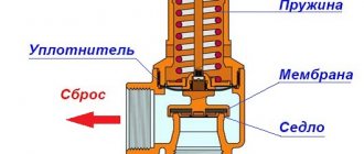
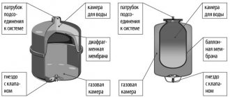
It is a steel structure, which is internally divided into two chambers. One of them is designed to be filled with water from the heating system, and the second serves as an air compensator. To set the optimal pressure in the air chamber, a valve is provided in the accumulator. With its help, the degree of air injection is changed, thereby adapting the device to the parameters of a specific heating system.
The chambers are separated by an elastic membrane or rubber balloon. When the water temperature in the pipes rises above critical, a pressure surge occurs. The liquid, expanding, begins to press on the walls of the separation membrane. She, in turn, under the influence of this force, increases the filling volume of the water chamber. This leads to normalization of pressure within the entire system.
Connection rules, diagram
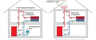
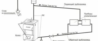
When installing a hydraulic accumulator, certain rules should be followed. First of all, you need to select an area in the heating main where it will be installed. Experts recommend installing the expansion tank in the return pipe with chilled water. But at the same time, it must be installed before the pumping equipment. The general installation diagram is as follows.
As you can see, a safety valve is installed at the outlet of the heating equipment to protect the line from differences in liquid pressure. It performs the same functions as a hydraulic accumulator, but is designed for higher pressure surges. An expansion tank is necessary to normalize heating operation at small pressure drops.
Before starting installation, please consider the following:
- Selecting an installation location. The main requirement for it is free access to the device. This is especially true for the air chamber control valve.
- There should be no other shut-off or control valves in the area between the pump and the expansion tank. It can make significant changes in hydraulic resistance.
- The temperature in the room where the accumulator is installed should not be below 0°C.
- Its surface should not experience mechanical stress or external influences.
- The response of the pressure reducer to release air from the chambers must be set according to the parameters of the heating system.
Guided by these rules, you can install the expansion tank yourself. But at the same time, you should follow the connection rules, use products made of high-quality material and calculate the optimal tank volume.
To make the calculation, you need to know the total volume of the heating system, the optimal and maximum pressure in it, as well as the expansion coefficient of water. Formula for calculating the size of a membrane-type hydraulic accumulator:
- e – water expansion coefficient – 0.04318;
- C – total volume of the heating system;
- Pi – initial pressure;
- Pf – maximum pressure.
Let's consider an example of a calculation for heating with a total volume of 500 liters, an optimal pressure of 1.5 bar, and a maximum of 3 bar.
In this case, it is optimal to choose a hydraulic accumulator with a total volume of 50 liters.
This technique will allow you to correctly select and connect an expansion tank for a closed heating system.
Design and principle of operation
Let's take a closer look at how this device works.
A hydraulic accumulator is a sealed metal container , inside of which there is an elastic membrane or cylinder.
Between these components and the walls of the casing, thanks to compressed air pumped into the free space, a pressure of a certain force is created.
Water has no contact points with the surface of the housing.
Because it is located in a special compartment called the membrane chamber.
It is made of rubber called butyl, which is not susceptible to the negative effects of pathogenic cocci.
In addition, this material meets the sanitary and hygienic standards that apply to drinking water.
There is a pneumatic valve in the air compartment . Its purpose is to regulate pressure.
The liquid penetrates into the accumulator through a special connecting nozzle with a threaded connection.
The device must be mounted in such a manner that, if repair or maintenance work is necessary, it can be quickly disassembled without draining the water from the system.
The cross-sections of the pressure pipe and the connecting pipeline must correspond exactly to each other.
Thus, it will be possible to insure against unforeseen hydraulic losses in the pipeline.
In the membranes of expansion tanks , the volume of which is 100 liters or more, a special spool is mounted, through which the air released from the water is released (read about Mayevsky’s automatic valve in this article).
In small-displacement hydraulic accumulators, such a valve is not provided.
The permissible pressure in the air valve of the device is 2 atmospheres.
Expansion tanks, hydraulic accumulators, for heating and water supply systems
Closed expansion tanks and hydraulic accumulators have approximately the same design: a durable metal shell, divided inside by a rubber membrane into two sections.
One section contains water, the other contains air. As water pressure increases, the air is compressed, the size of the section with air decreases, and the membrane bends, water displaces the air. The device has a connection to the water supply system on one side, and a spool valve for pumping air on the other.
But devices are named not because of their design features, but according to their intended purpose.
Purpose
- Expansion tanks are designed to compensate for the expansion of water due to heating in heating circuits, as well as hot water supply (DHW).
- Hydraulic accumulators are designed to accumulate volumes of water under pressure in water supply systems that have a pressure pump, to reduce the frequency of switching on of this pump and to smooth out water hammer. An additional function is a supply of food-grade water up to 1/3 of the total tank volume.
The nuance is that the same device is used for both hot and cold water supply, but it can be called differently, depending on what it does in a particular circuit - it either accumulates (accumulates) a supply of water, or takes its excess during thermal expansion.
- The design feature of the hydraulic accumulator is often that inside there is not a membrane, but a bulb made of food-grade rubber, which is pumped with water. Water does not come into contact with the tank body.
- The expansion tank for the heating system is made of a membrane made of technical rubber, which divides the housing into two compartments, and the coolant (not always water) is in direct contact with the housing.
How to differentiate
In appearance, all membrane tanks are similar to each other. There is an opinion that for the heating system - red, and for water supply - blue. But it is not entirely true, since some manufacturers use other colors.
In fact, devices can be distinguished from each other only by technical characteristics, which are indicated on the nameplates on the devices themselves:
- All devices for water supply, including for hot water supply - low temperature - up to 80 degrees C, but high pressure - up to 12 Atm;
- expansion tanks for heating - high temperature - up to 120 degrees C, but low pressure up to 4 Atm.
How water storage schemes work
The hydraulic accumulator in the water supply circuit smoothes out pressure surges that occur when water is drawn from the system, i.e. when opening the tap, and reduce the number of pump starts, which should not be more than 50 times per hour.
When water is taken in the volume of a cup, the hydraulic accumulator will release this volume, the pressure in the system will drop, but not so much that the pressure switch turns on the pump. When taking a larger volume (for example, the volume of a bucket), the pressure will drop so much that the pump will turn on and fill the device.
The expansion tank in hot water supply and heating systems receives the excess volume of water that arises when it is heated.
If there were no such device, then in a heating closed circuit the pressure would very quickly rise above the critical one, since the liquid is practically not compressed. This would result in the release of water from the emergency pressure valve, which is usually set to a pressure of 3 atm.
In practice, if such a valve constantly lets water through, this indicates a malfunction of the storage device. If there is no emergency valve, then when heated, the weakest point of the system will be destroyed.
When an expansion tank is needed in a hot water supply system
This is a natural question, because hot water supply can be done in different ways. If there is a flow-through heater, for example a gas double-circuit boiler, which heats a stream of water directly when it is drawn in, then naturally an expansion tank is not needed.
If the system heats water in a large-capacity closed boiler (more than 100 liters), then the installation of an expansion tank in addition to a safety valve is required. Which is not the right thing to hope for, since it is not at all designed for frequent operation and with frequent activation it simply begins to leak.
How to choose the volume of a heating device
The main question that arises for the user is how much volume of such a water storage device is needed? At the same time, the user wants to purchase a smaller volume, since it is cheaper. But you need to purchase the one that suits your calculations.
Calculation of the volume of a hydraulic accumulator tank
The role of a hydraulic accumulator (expansion tank) in an autonomous water supply system at home
3 points of consumption
Let's start with the fact that if your house only has a water tap, a shower and a water tap, then you don’t need to count anything.
You need a standard water supply station with a 24-liter accumulator. Don't hesitate to buy it. It is optimal in cases where equipment for a small house (dacha) with periodic (irregular) use is being considered. Even if in the future you need to increase the number of water collection points, you can simply buy separately and install another 24 liter hydraulic accumulator at any point in the water supply system. More than 3 points of consumption
If the house does not have a sewer system, but has more than three water points, then a 50 liter hydraulic accumulator will be sufficient for you.
Below is a calculation methodology for individual houses equipped with a sewerage system (septic tank), with bathrooms and other equipment that consume a significant amount of water.
1. The total coefficient of water consumption Su should be determined
. To do this, make a list of water distribution points in your home and indicate the quantity of each type of equipment. Below is a table of “normal” water consumption for various household appliances.
| Consumers | Normal consumption | |
| l/m | m3/h | |
| Bath | 23 | 1,38 |
| Shower | 12 | 1,08 |
| Washbasin | 3,5 | 0,21 |
| Kitchen sink | 10 | 0,6 |
| Washing machine or dishwasher | 10 | 0,6 |
| Toilet cistern | 10 | 0,6 |
| TOTAL | 74,5 | 4,47 |
2. To determine the volume of the hydraulic accumulator, it is necessary to decide how many times per hour the hydraulic accumulator can be turned on at maximum consumption intensity
. 10-15 times is considered normal. Please note that a large value of this parameter (some companies recommend setting this parameter at a maximum intensity of up to 45 starts per hour) leads to frequent loading of the accumulator membrane by tension and compression, and the total number of such loads is limited by the strength of the membrane. In addition, if 45 starts per hour, this means that the pump only runs for about a minute before shutting down. Typically, the performance of household pumps in individual water supply systems is small, and it is simply impossible to fill a correctly selected hydraulic accumulator in a minute. Our recommendation for assigning this parameter is 10.
When checking the possibility of using an existing hydraulic accumulator in cases where a new source of water consumption is added to the house, this parameter can be taken equal to 15.
It is also necessary to assign response thresholds for the pressure switch of the water supply station (Pmin and Pmax). The lower threshold Pmin for two-story houses is usually 1.5 bar, and the upper threshold Pmax is 3 bar. Then, to determine the volume of the accumulator, you must use the following formula:
where V is the total volume of the accumulator, l; Omax – maximum value of required water flow, l/min; A – number of system starts per hour; Pmin - lower min pressure threshold when turning on the pump, bar; Pmax is the upper pressure threshold when the pump is turned off, bar; Po – initial gas pressure in the accumulator, bar.
For example, if Qmax = 36 l/min, A = 15, Pmin = 1.8 bar, Pmax = 3 bar, Po = 1.8 bar, then the total volume of the accumulator:
The number of such loads is limited by the strength of the membrane. In addition, if 45 starts per hour, this means that the pump only runs for about a minute before shutting down. Typically, the performance of household pumps in individual water supply systems is small, and it is simply impossible to fill a correctly selected hydraulic accumulator in a minute. Our recommendation for assigning this parameter is 10.
When checking the possibility of using an existing hydraulic accumulator in cases where a new source of water consumption is added to the house, this parameter can be taken equal to 15.
The closest in size is a 150 liter hydraulic accumulator.
Next, we will present our recommendations for assigning response thresholds for pressure switches in water supply systems of an individual home. The difference in response thresholds Pmax - Pmin determines the volume of water supplied by the hydraulic accumulator of the water supply system. The greater this difference, the more efficient the operation of the accumulator, but the membrane is more heavily loaded in each operating cycle.
The Pmin value (pump activation pressure) is determined based on the hydrostatic pressure (water height) in the water supply system of your home. For example, if the height between the lowest and highest sampling points in the system is 10 m, then the pressure of the water column is 10 m (1 bar). What should be the minimum pressure value Pmin? The air pressure in the backpressure chamber of the hydraulic accumulator must be greater than or equal to the hydrostatic pressure, that is, in our case, 1 bar. The lower response threshold Pmin should then be slightly higher (0.2 bar) than the initial air pressure in the accumulator.
However, we need the system to work stably. The most critical, from the point of view of stability of operation, is the highest point of analysis (for example, a faucet or shower on the top floor). The tap operates normally if its pressure drop is at least 0.5 bar. Therefore, the pressure should be 0.5 bar plus the hydrostatic pressure at that point. Thus, the minimum value of the gas pressure in the hydraulic accumulator Po is equal to 0.5 bar plus the value of the reduced hydrostatic pressure at the location of the hydraulic accumulator (the height distance between the upper point of disassembly and the point of location of the hydraulic accumulator). In our case, if the accumulator is located at the lowest point of the water supply system, the minimum gas value in it is Po = 1 bar + 0.5 bar = 1.5 bar, and the response threshold (switching on) of the pump is Pmin = 1.5 + + 0, 2 = 1.7 bar. If the hydraulic accumulator is located at the top point of the system, and the pressure sensor is at the bottom, then the gas pressure in the hydraulic accumulator should be 0.5 bar, and the pump activation threshold should be 1.7 bar.
When assigning the upper threshold for operation of the automatic water supply system Pmax, it is necessary to take into account several points, first of all, the pressure characteristics of the pump. The pressure generated by the pump, expressed in meters of water column, divided by 10, will show the maximum pressure value. However, it should be taken into account that:
- the pump characteristics indicate the maximum parameters without taking into account the hydraulic resistance of the pipelines;
- the electrical network voltage often does not correspond to the nominal value of 220 V, and actual values may be lower;
- Manufacturers of household pumps often indicate overestimated characteristics;
- at maximum pressure values, the pump flow rate is minimal and the system will fill for a very long time;
- with prolonged use, the pump characteristics decrease.
Taking into account the above, we recommend setting the upper threshold value 30% lower than the maximum pressure value of your pump. However, the initial factor when determining the upper trigger threshold is the height of your house, or rather, the height of the house’s water supply system. The value of the upper threshold is equal to the height of the water supply system (expressed in meters) plus 20 m, divided by 10. You will get the pressure expressed in bars.
In domestic water supply systems, the recommended difference between the lower and upper response thresholds is 1.0-1.5 bar. These values are the most acceptable. Thus, to determine the upper threshold of the pump activation pressure, we recommend:
- determine the lower pressure threshold for turning on the pump;
- add 1.5 bar to the obtained value;
- Compare the obtained value with the pressure characteristics of the pump.
It should be 30% below the maximum pressure of your pump. In this way, you can check the correct selection of the pump and accumulator or the possibility of using existing additional equipment that consumes water during installation.
Buy
a hydraulic accumulator in the AQUARIUS online store at a great price. In our store you can get advice on the selection of any type of pumping equipment and additional equipment for organizing autonomous water supply at home.
We also recommend reading
- How to choose a pumping station?
- Connection diagram of the pumping station with tank No. 1
- Connection diagram of a vortex centrifugal pump for autonomous water supply of a private house No. 5
What is a hydraulic accumulator (HA)
It is unknown why this happened, but many authors believe that the heating accumulator is an expanzomat. And such a paradox is observed all the time. Well, why would an expansion tank, which only compensates for the expansion of water, be a hydraulic accumulator for heating systems?
If we are careful, the name itself already tells us that this device must accumulate liquid. Two devices meet this characteristic:
- hydraulic accumulator for cold water (expansomat);
- buffer capacity in the heating circuit (heat accumulator).
It is important not to confuse expanSomat with expanZomat (expansion tank). Perhaps this confusion lies in the similarity of names? It turns out that if we consider only the heating system, then the only hydraulic accumulator in it is the buffer tank. Although it is not intended for storing water, it fully corresponds to its name. Since there is still water in it and it heats up during the operation of the boiler, that is, it accumulates heat. After the heater stops working, the hydraulic accumulator for heating systems releases all the energy that it could accumulate.
The amount of this energy directly depends on the volume of the buffer tank. Accordingly, the more water it contains, the more heat it can hold. We’ve decided on the terminology, now let’s take a closer look at how it all functions.
How does a water heat accumulator work?
A water accumulator for heating performs the following tasks:
- energy storage;
- stabilization of the temperature of the working fluid;
- reducing the number of furnace loads;
- increasing boiler efficiency;
- reduction of fuel consumption.
How can one device perform so many functions? In fact, everything is quite simple, because all these processes are interconnected.
As a result of using a heat accumulator, you get some advantages. Your system will be stable, and its operation will be less troublesome, because adding firewood every four hours is not an option for permanent housing.
The accumulation of energy occurs in those moments when the fire burns. In the absence of a HA, the water in the circuit can heat up beyond what is necessary, because there is nowhere to put the excess heat. And after combustion stops and the fuel begins to smolder, the temperature of the working fluid decreases. It turns out that surges constantly occur in the batteries, and accordingly, in the room too. In general, nothing good.
How to choose a hydraulic accumulator
When it comes to choosing, then thoughts arise about whether to make a hydraulic accumulator for heating with your own hands. In fact, there is no difficulty in this, at least if you are not going to install additional low-temperature heating and hot water circuits, as well as electric heating. The main thing is that the container is sealed and, if possible, insulated. The insulation layer will reduce heat loss, which will increase the efficiency of the heat accumulator. Below is the simplest design of a heat accumulator:
The most primitive accumulator circuit
The shape of the tank can be any, as long as the pressure in the circuit does not exceed three atmospheres. And in an autonomous heating system this condition is met. The pressure in the hydraulic accumulator of the heating system is the same as in the entire circuit. Even automatic emergency valves are designed to withstand this pressure. So the shape depends more on where you put it. In general, do whatever is convenient for you.
You can add a DHW circuit. To do this, you need to weld two pipes into the upper part of the tank. A spiral is attached to them from the inside, through which water will circulate. The spiral must be in the upper part, as it is warmer there. The scheme is approximately like this:
Diagram of a hydraulic accumulator with a DHW circuit
The longer the tube you insert to heat water for household needs, the more it will warm up. The advantage of a homemade buffer tank is that you can always improve it, for example, add heating elements that will operate from the network or from solar panels. In this case, it is better to place heating elements in several places. This arrangement of additional heaters allows for a more even distribution of temperature in the tank.
Connecting the hydraulic tank
A hydraulic tank is the second name for a hydraulic accumulator. It can be connected to the water supply system in various ways. The choice of a suitable connection scheme mainly depends on the capacity in which the device will be used, as well as what tasks it will perform. It is worth considering several of the most popular connection methods.
Using a surface pump
It is worth examining step by step how the hydraulic accumulator is connected to the system if there is a surface pump subtype.
- First you need to check the air pressure in the inside of the tank. It should be 0.2-1 bar less than the parameter on the relay.
- Then you should prepare the equipment for connection. In this situation, the equipment means: a fitting, a pressure gauge, a tow with a sealing compound, a relay responsible for pressure.
- You need to connect the fitting to the tank. The connection area can be a hose or a flange with a bypass valve.
- Then you should screw on the other devices one by one.
To determine the absence of leaks, you need to run the equipment in test order
When connecting the relay, which is responsible for regulating the pressure, it is important to inspect all the marks. Under the cover there are contact connections - “network” and “pump”
Do not confuse the wires. If there are no marks under the relay cover, then it is better to contact a professional to connect it to avoid a serious mistake.
With submersible pump
The submersible or deep-well type of pump differs from the above option in that it is located in a well or dug well, in other words, in the area from which water is sent to the home, and in the above situation, to the hydraulic accumulator. One detail is very important here - the check valve. This element is designed to protect the system from liquid penetration back into the well or well. This valve is fixed on the pump next to the pipe. For this purpose, a thread is cut in its lid.
First of all, fix the check valve, and then connect the hydraulic accumulator itself to the system.
The diagram is as follows:
to measure the length of the pipe running from the deep-well pump to the extreme point of the well, you basically take a string with a weight; the load is lowered to the bottom, and a mark is made on the rope to mark the edge of the well at the top; after removing the rope, you can calculate the length of the pipe from the lowest plane to the top; you need to subtract the length of the well, as well as the distance from the section where the pipe passes into the soil to the highest level of the well; In addition, it is very important to take into account the immediate location of the pump (pump) - it should be located 20–30 cm from the bottom.
How to connect a water battery
Let's start with the fact that the buffer tank is always located between the boiler and the heating system, that's why it is a buffer. Tying can be done in different ways. This applies to both connecting the tank to the boiler and to the heating circuit. Here you can experiment a little, the main thing is that the coolant flows move along the required vectors. The heat accumulator is installed in two types of systems:
- gravitational;
- with forced circulation.
Here is a simple diagram for installing a hydraulic accumulator in a sealed heating system with a closed expansion tank:
Installation of a hydraulic accumulator in a closed heating system
It should be said that if the electricity goes out, the circuit will not function without an alternative power source. The same cannot be said about the gravitational circuit. Below is a heating diagram with a hydraulic accumulator (connection to the heater):
Scheme of gravity heating with hydraulic accumulator
Please note that the tank is located above the boiler level. The wiring of the circuit from the tank to the batteries should be carried out at an angle. This can be done using a one-pipe or two-pipe scheme. We wrote about heating pipe wiring diagrams a little earlier. In principle, the second scheme will be applicable (even more preferable) for sealed circuits. In this case, the boiler has a so-called heating kennel.
The heating circuit is a small boiler piping ring. It is needed so that the water in the circuit heats up faster. As soon as the boiler turns on, water heating begins. If there is no heating ring, then the coolant immediately goes into the heat accumulator, and from it into the circuit pipes. At the same time, cold water from the return flow enters the boiler. It turns out that while the batteries become warm, the boiler must warm up a lot of liquid.
If there is a heating circuit, then water does not enter the system until it reaches a certain temperature. This value is controlled by a thermostatic valve and is approximately 60 degrees (depending on setting). When the water gets hotter, the valve mixes in coolant from the bottom of the buffer tank. It turns out that warm water always flows into the circuit and the tank is charged, which is what we need.
How to properly adjust the pressure in the accumulator
In order for the pumping unit to operate stably, it must be configured correctly. There are 3 main parameters:
- The pressure level after which the pump begins pumping water.
- Installation shutdown threshold.
- Air pressure in the tank.
Parameters 1 and 2 are controlled by a pressure switch. A special device is installed on the battery input plug. The adjustment occurs experimentally; to reduce the error, the steps should be repeated several times. The relay design includes 2 springs. They are mounted on vertical rods and screwed with nuts. The springs differ in size and functionality: the large one is responsible for regulating the pump on and off, and the smaller spring regulates the difference between the upper and lower pressures. The springs are connected to a special membrane, which closes and, accordingly, opens electrical contacts.
Adjustment is made using a key. The required nut must be turned clockwise. This leads to compression of the spring and an increase in the pump activation threshold. Turning counterclockwise accordingly weakens the spring. There is a step-by-step adjustment scheme:
- First you need to check the air pressure in the battery and pump it up with a compressor.
- Next, turn the nut over the larger spring to the optimal level.
- The tap is turned to drain the liquid. The pressure, naturally, should drop, after which the hydraulic pump turns on. The indicators are remembered. If necessary, the series of actions is repeated again.
- Next, the small spring is adjusted. It should be remembered that it is very sensitive to adjustment, and therefore it is better to turn it 0.5 turns.
- The indicator is recorded with the taps and working hydraulic pump closed. The device will display the value at which the equipment will stop working. If it is more than 2 atm, then you need to slightly turn the small spring in the opposite direction.
- It is necessary to drain the fluid and restart the hydraulic pump. The process must be repeated until the best measurements appear.
Installing a hydraulic accumulator in a heating system
Find out the cost of repairs
Repair work?
Why do clients choose us?
Heating and Repair
We have the best prices!
The heating design includes wires or pipes, circulation pumps, a fastening system, an expansion tank, a heating boiler, radiators, thermostats, fittings, automatic air vents, and a heat control mechanism. On this page of the site we can determine the necessary heating components for your cottage. Any element is definitely important. Therefore, the selection of parts of the system must be done wisely. Assembling a summer cottage heating system has certain elements.
Hydraulic accumulator in the heating system
A stable, properly functioning water supply network is a real merit of the owner of a country house. Anyone who has been involved in the installation and maintenance of an autonomous system knows how difficult it is to foresee water supply failures that are dangerous for household appliances. One pressure surge and there is a risk of damage to the dishwasher or gas water heater. To prevent possible problems, you need to contact a specialist or connect the hydraulic accumulator yourself.
Before you start connecting the accumulator, you need to become familiar with its component parts and the purpose of each of them.
Blue hydraulic accumulators are intended for water supply systems. Expansion tanks for heating systems are red
Diagram of the hydraulic accumulator: 1 – metal body, 2 – membrane. 3 – flange with valve, 4 – nipple for air injection, 5 – compressed air, 6 – legs, 7 – platform for pump
A hydraulic accumulator is a metal reservoir, inside of which there is a rubber membrane in the shape of a pear. A rubber (caoutchouc) membrane is attached to the body with a flange and a pipe.
The hydraulic accumulator stores water under pressure. Pressure in household appliances (1.5 bar) is created using air, in industrial models - inert gas.
Compressed air can be pumped into the housing using a bicycle or car pump. When water enters the tank, the compressed air prevents the bulb from bursting by providing resistance. It is also used to regulate the pressure in the hydraulic accumulator. During the water collection process, water moves from the apparatus into the system.
Hydraulic accumulators are somewhat different in their purpose, so they can be divided into 3 types:
- For cold water. Supplies and stores water, protects equipment from water hammer during pressure surges. Protects the pump from wear and tear during frequent starts.
- For hot water. Its difference is its ability to function in high-temperature environments.
- For heating systems (expansion tanks). They are an important part of closed heating systems.
The pump pumps water from a well, a well or a water supply system through pipes into a hydraulic accumulator, or more precisely, into a rubber membrane inside it. The process continues until the pressure reaches a certain point. The required pressure is set on the relay regulator, usually 1-3 atmospheres. When the required pressure is reached, the pump turns off (automatically).
Suppose you turn on a washing machine, shower or faucet in the kitchen - water from the membrane immediately flows back into the pipes. At the moment when the pressure reaches the lower threshold, the relay is activated and turns on the pump again. Thus the cycle begins again.
The video below will give a complete picture of how the accumulator works:
The frequency at which the pump is turned on directly depends on the volume of the accumulator. The larger its tank, the less often the pump turns on. Accordingly, the less often the pump is turned on, the longer both the flange with the valve and the pump itself last. The equipment is placed on the floor or mounted on the wall. In any case, its body does not suffer from use.
Let's consider step by step how to connect a hydraulic accumulator to a water supply system if a surface-type pump is used.
- Checking the air pressure inside the tank. It should be 0.2 - 1 bar less than the indicator indicated on the relay (to turn on the pump).
- Preparation of equipment for connection: a fitting with 5 outputs (used to connect a hydraulic accumulator, relay, pump and pressure gauge; another outlet, the fifth, is necessary to connect a water supply pipe); pressure gauge; tow with sealant or FUM tape; relay for pressure regulation.
- Attaching the fitting to the tank. The connection point can be either a rigid hose or a flange equipped with a bypass valve.
- Screwing the remaining elements one by one: relay, pressure gauge, pipe leading to the pump.
Optimal performance
The functioning of the water supply network and the life of the storage tank depend on several factors:
- The correct choice of the maximum and minimum pressure at which the automatic switching on of the pump is triggered.
- Correctly setting the air pressure level in the tank.
When performing independent checks and adjustments of indicators, you should follow the recommendations of specialists. The basic rule is that the air pressure in the hydraulic storage tank must be lower than the minimum pump start pressure. The difference in indicators is 10-12%. Following the recommendation allows you to save a small amount of water until the next time you turn on the unit. Example: if the pumping station automatically starts working at 2 bar, the air pressure should be 2-0.2=1.8 bar.
The air pressure in the storage tank does not depend on its volume. The average for containers measuring 24-150 l is 1.5 bar, 200-500 l - 2 bar. The initial factory air injection of 1.5 atmospheres in conditions of low water consumption of a one-story building can be reduced to 1 atmosphere. Low pressure in the pipes reduces wear and tear on the system, but limits the use of plumbing fixtures. Reducing the pressure to less than 1 bar will result in excessive stretching of the rubber bulb. The membrane will come into contact with the metal casing. Contact will cause accelerated wear of the rubber.
Excessive air pressure (more than 1.5 bar) is also not desirable. It will take up most of the tank, reducing the amount of water drawn. There will also be an increased load on the pipes and components of the water supply system.
The water pressure in the membrane is created by a pump. Its maximum permissible value is indicated by the manufacturer. A common indicator for household models is 10 bar. When connecting a hydraulic accumulator to the system, liquid is supplied slowly to avoid damage to the membrane.
Pressure calculation
To calculate the optimal air pressure in the tank, there is a formula: P=(Hmax+6)/10, where
- P – air pressure in atmospheres;
- Hmax is the distance to the highest point of the home water supply network.
The highest point of analysis is the shower on the top floor of the building. The distance from it to the installation site of the pressure tank is measured. The larger the gap, the higher the pressure required to lift the water. The use of numbers will add clarity to the calculation. For a building with a height of 2 floors, the Hmax value will be 7 m. The pressure will be P=(7+6)/10=1.3 atmospheres. For a height of 10 m, a pressure of 1.8 atmospheres is required.
Before purchasing a hydraulic accumulator, the volume of the device is calculated. Calculations take into account:
- maximum water flow;
- number of pump starts per hour;
- air pressure in the tank;
- lower and upper pressure limits for pump activation;
- coefficient related to pump power.
After installing the membrane tank, you will need to set the minimum and maximum threshold for the automation (pressure switch). The volume of water coming from the hydraulic accumulator depends on the difference between the maximum and minimum indicators. Increasing the parameter increases the efficiency of the device, but leads to rapid wear of the membrane. For private houses, a difference of 1-1.5 bar is recommended.
The minimum pressure in the membrane (Pmin) should be 10% higher than that of the air in the tank cavity. For stable operation of the system, the pressure drop must be 0.5 bar or higher. This value is taken into account when calculating Pmin. The upper response limit (Pmax) is calculated based on the characteristics of the pump - the pressure value is divided by 10. The calculated value does not correspond to the real one due to changes in the declared parameters of the unit associated with wear. It is recommended to take the upper level indicator 30% less than the pressure characteristic.