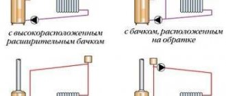
Dependent heat supply scheme
If you imagine the elevator unit of a residential building (you can see what it looks like in the photo), then it is arranged as follows:
- the elevator is separated from the heating main by inlet valves;
- behind them, at the supply and return points, valves or gate valves are located. Hot water supply is connected through them from the supply or return pipelines. Often in modern elevators there are two taps on the supply and return lines, which are separated by a retaining washer. Their purpose is to ensure constant circulation of hot water;
- after inserting the elements to provide DHW, there is a nozzle with a chamber where mixing is carried out. The flow of hotter liquid coming from the direct pipeline under high pressure heats up part of the water in the return and is sent for recirculation;
- house valves shut off the heating system of the building - they are open in winter and closed in the warm season.
Dependent and independent heating systems differ in that in the first version, water enters the hot water supply and heating systems directly from the heating main.
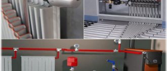
Installation diagrams for electrical consumption points
Any electrical system includes many elements that must be created in accordance with modern legal standards.
During the development of electrical projects, specialists create professional diagrams for connecting points of consumption - sockets, lamps and switches. When determining the installation locations for consumption points, designers should be guided by the data contained in the technical specifications provided by the owner. The terms of reference is a very important document, since it must contain the parameters of all electrical devices that will be used by residents at the site, the location of electrical appliances and furniture, as well as all the wishes of the house owner regarding the features and functionality of the future electrical system.
An example of an electrical circuit in a house
Back
Forward
Independent heat supply scheme
An independent heating circuit looks like this:
- From the supply pipeline, the liquid enters the return line, simultaneously transferring thermal energy to the heat exchanger. In this case, water is not used for hot water supply and space heating;
- the same heat exchanger, but its other circuit, receives drinking water from the water supply. After heating, it is supplied to the heating system and for domestic use.
This is what an independent heating system connection looks like.
SCHEMES FOR CONNECTING HEAT CONSUMERS TO HEAT NETWORKS
Connection of water heat supply systems to consumers is carried out through central heating points (CHP) or individual heating points (ITP). Central heating points supply coolant to a group of buildings (Fig. 3.1.16) [35], individual heating points serve one building or part of a building.
Rice. 3.1.16. Heat supply diagram for a group of buildings from central heating stations
The heating point ensures the receipt of coolant from the heating network, its preparation for use by the consumer and the return of the waste coolant to the heating network. Often the coolant parameters (temperature, pressure) required by the consumer differ from the coolant parameters in the heating network. One of the tasks of heating points is to reduce the parameters of the coolant to the level required by the consumer. The equipment of a heating point includes centrifugal pumps, elevators, shut-off valves, devices for metering thermal energy and the amount of coolant, mud collectors to protect the heating system from contamination, filters and other devices to protect hot water supply systems from corrosion. If the connection of consumers to the heating network is carried out according to an independent scheme, then water heaters, usually sectional or plate-type, are installed at the central heating substation (or at the ITP). The latter are much more thermally efficient and have significantly smaller dimensions, however, they are expensive and require cleaning of the channels between the plates for the passage of water when they become clogged.
According to the method of connecting hot water supply systems, water heating systems are divided into open and closed. If the water circulating in the heating network is not taken from the network, the heating system is called a closed heating system. Water in such a system is used only as a coolant.
A water heat supply system, in which water is completely or partially taken from the system by thermal energy consumers, is called an open heat supply system. Water in such systems is used not only as a coolant, but also for hot water supply and for technological needs.
Consumers of heating and ventilation heat loads are connected to the heating network using a dependent or independent circuit. In a dependent scheme, water from the heating network directly enters the heating devices of heated premises or into air heaters to heat the supply air of ventilation systems.
When using an independent circuit, the connection is made through heat exchangers, in which the water circulating in the circuit of the local system is heated. In this case, the pressure in the local system does not depend on the water pressure in the heating network and is created due to the operation of the pump installed in it. Independent connection schemes are more complex and expensive. They are used in special cases, for example for heating multi-storey buildings. An important advantage of open systems is the ability to use the heat of low-potential secondary energy resources generated in production (with a temperature of 30-40 ° C) to heat water used for hot water supply.
Schemes for connecting heat consumers to the water heating network are shown in Fig. 3.1.17 [35].
In Fig. 3.1.17, A shows a diagram with direct supply of network water to heating devices
In Fig. 3.1.17, B shows a diagram with an elevator - a mixing device that ensures mixing of water from the supply pipeline and the return pipeline of the heating network. This makes it possible to reduce the temperature of the water supplied to the consumer’s heating devices to the values defined by sanitary standards. For residential consumers, this temperature is 95 °C.
If the pressure at the input of the heating network is insufficient for the operation of the elevator, then a scheme is used in which water circulation is provided by a pump, see 3.1.17, B.
The connection schemes described above to consume lei are dependent. An independent connection diagram is shown in Fig. 3.1.17, D. Connection is carried out through a water-to-water heat exchanger. An expansion tank is installed in the local system, in which it creates its own independent* hydrostatic pressure.
In Fig. 3.1.1 7, D shows a closed connection system for a hot water supply system. As in the previous case, heat is transferred to water through a water heater. The system includes a hot water heat accumulator, which is necessary to smooth out fluctuations in water flow as its consumption increases.
A B C D E
Rice. 3.1.17. Schemes for connecting heat consumers to the heating network:
A—system with direct connection; B—cleaning system with elevator connection; B—heating system with pump mixing; G— heating system with independent connection; D—closed hot water supply system.
Central heating points of steam heat supply systems are provided at the points where steam pipelines enter an industrial enterprise.
In cases where the operation of process units requires high-pressure steam (over 3 MPa), as, for example, at chemical or petrochemical enterprises, their connection to steam pipelines can be carried out bypassing the central heating station.
Dependent and independent heating system - comparison
The advantage of a dependent heating connection scheme is that the cost of its implementation is inexpensive.
The fact is that if the house has a small area, the elevator unit of the heating system for it can be installed independently, using conventional shut-off valves. The most expensive part to manufacture is the nozzle; the thermal power of the elevator depends on its diameter. The advantages of an independent heat supply scheme:
- it allows you to more flexibly regulate the temperature of the heating fluid. To do this, it will be enough to reduce the flow of coolant through the heat exchanger and, as a result, the air temperature in the house will drop. You can also press the valves in the elevator unit and thereby remove the difference. Such a design of the elevator heating unit will allow you to avoid many problems. But for these elements, such a situation is considered abnormal, since the cheeks may fall and circulation may stop. If the system is independent, the performance is simply regulated - using a circulation pump;
- efficiency is a consequence of the availability of flexible heating settings depending on the needs of residents. In a dependent system, this indicator is no more than 40%;
- an independent heat supply system allows you to use water purified from impurities or non-freezing liquids as a coolant (more details: “Non-freezing liquid for heating systems - making the right choice”). It is not difficult to heat drinking water for domestic hot water. In turn, in the presence of a dependent system, consumers are forced to use water with large contaminants - sand, scale and mineral salts.
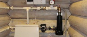
Solid fuel boilers
The heat generator, which is a boiler (steel or cast iron) with a water jacket in the firebox and mechanical adjustment of the blower using a thermostat, is a completely energy-independent device.
True, this design has a serious drawback, which is that it requires constant additional loading of solid fuel. Several technical solutions help to make independent heating of a private home, that is, without involving people:
- Installation of hopper and transport belt. As the fuel burns out, new portions of pellets or sawdust will be supplied. But the conveyor requires electricity to operate.
- Using a pyrolysis boiler, in which the combustion process is divided into two stages. The first of them is the pyrolysis of wood with a limited supply of oxygen, and the second is the combustion of the resulting gas. At the top there is a pyrolysis chamber, and below it there is a compartment where the gas burns. At the same time, in order for the combustion products to move against the direction of natural draft, an electric fan is needed.
- A top-burning boiler can operate on one bed of coal for about five days, since only its top layer smolders. Air is supplied to the fuel from top to bottom, and the ash is carried away by the hot flow of combustion products. But to ensure air circulation, you will need an electric fan.
Installation of transformer substations (TS) – LLC Center for Energy Solutions and Innovations
In this case, the resistance of the wire decreases sharply, and the overvoltage wave is discharged into the ground.
You can be confident in the high quality of work if you trust us with the power supply of your enterprise. In normal operation, one of the jumper disconnects should be disabled. The voltage windings of measuring instruments and relays are powered from a voltage transformer T V, connected to the busbars through a high-voltage finger-type contact.
The F V3 arrester, which protects the insulation of kV switchgear equipment from overvoltages, is located on the same withdrawable trolley as the TV voltage transformer. It receives power from one side of the electrical grid.
The main circuits supply power to outdoor lighting fixtures BUT; According to radial circuits, electricity is supplied from the transformer substation TP to individual receivers, for example, to the concrete mixing department - BSO, to the tower crane - BC. Schemes of powerful node substations On the kV buses of node substations, the connection of individual parts of the power system or the connection of two systems is carried out, therefore, increased reliability requirements are imposed on the circuits on the HV side. A second manually operated jumper disconnector QS4 is used when repairing QS3 to create a visible circuit break. Transformer T2 remains in operation, receiving electricity from input W2.
Diagram of switchgear kV terminal and branch substations A single-line diagram of switchgear kV of a pass-through substation included in the cutting of the kV line is shown in Fig. The project is developed by a licensed organization on the basis of the technical conditions and technical specifications issued by the technical specifications and can be standard or individual.
In both cases, complete devices are used, consisting of cabinets or chambers in which switches and current transformers are located. The packaging must contain instructions for installing the substation, as well as recommendations for its use. To make these changes to electrical circuits possible, their elements - transformers, switchgear buses, overhead and cable lines - are connected to each other through switching devices.
Available for: - closed installations. Each phase of a three-phase switch is located in a separate steel cylinder pot 3, mounted on support insulators 2 mounted on a common grounded steel frame 1. Nowadays, many enterprises that manufacture substations not only deliver equipment, but also install it. scheme apartment 2 TP
Which heating scheme is better?
If your home experiences frequent power outages, it is preferable to install a non-volatile gas heating boiler, since it can be used without electricity. But it should be noted that these devices are not particularly economical: to maintain a pilot flame, about 20% of the consumed volume of gas is consumed.
There is another drawback with gas non-volatile heating boilers - they do not have the ability to control the weather and control the unit using an external thermostat, which determines the temperature regime, for example, in the most remote room. Accordingly, it is not possible to program the temperature for a long period, for example, two weeks.
When you need to make a choice which dependent and independent heating system is better, it should be noted that the first of them has become unclaimed today.
At the same time, it must be said that in modern construction, an exclusively independent heating system connection scheme is used, despite significant financial costs.
Now everyone is switching to independent heat supply. In some cases, a combined scheme for connecting a heating point is used, using dependent and independent systems. About the types of heating systems in detail in the video: