Purpose
Plate heat exchangers are devices used to transfer thermal energy from one (hotter) stream to another (cooler) stream through thin metal plates separating them, which are pulled together by pressure plates to form a single structure.
Plate heat exchangers improve energy efficiency because energy from streams already in the system can be transferred to another part of the process rather than simply wasted. In the new era of sustainable development, the growing pressure to save energy and reduce overall environmental impact has placed greater emphasis on the use of heat exchangers with higher thermal efficiency. In this new scenario, the plate heat exchanger can play an important role.
Story
Plate heat exchangers were first introduced in 1923 for the pasteurization of milk, but are now used in many applications in the chemical, petroleum, climate control, refrigeration, dairy, pharmaceutical, food and medical industries. This is due to their unique advantages such as flexible thermal design (plates can simply be added or removed to meet different thermal or processing requirements), ease of cleaning to maintain strict hygienic conditions, good temperature control (necessary in cryogenic processes) and better heat transfer characteristics.
Types of plate heat exchangers
A plate heat exchanger (PHE) is a compact type of heat exchanger that uses a series of thin plates to transfer heat between two fluids. There are four main types of PT:
- collapsible,
- soldered,
- welded
- semi-welded.
A plate collapsible heat exchanger is a device in which the main function of heat transfer between coolants is performed by a stack of plates. The media do not mix with each other thanks to the alternation of plates with dense rubber gaskets, which form two movement circuits (Figure 1).
Figure 1 – Gasketed plate heat exchangers
This type of unit received its name “collapsible” because the package of plates is not only assembled, but also disassembled during regular maintenance (washing) or repairs.
Design and principle of operation
A plate heat exchanger (PHE) ensures the transfer of heat from a heated coolant to a cold one, without mixing them, decoupling the two circuits from each other. The coolant can be steam, water or oil. In the case of hot water supply, the heat source is often the heating fluid of the heating system, and the heated medium is cold water.
Structurally, the heat exchanger is a group of corrugated plates assembled parallel to each other. Between them, channels are formed through which the coolant and the heated medium flow, and they alternate layer by layer without mixing. By alternating the layers through which fluids of both circuits flow, the heat exchange area increases.
Heat exchanger operating diagram
The corrugation of the bowl is performed in the form of waves, moreover, oriented so that the channels of one circuit are located at an angle to the channels of the second circuit.
The connections of the inputs and outputs are made so that the liquids flow towards each other.
The surface and material of the plates are selected based on the required heat transfer power and the type of coolant. In particularly efficient and sophisticated heat exchangers, the surface is shaped to generate vortices near the surface of the plate, increasing heat transfer without creating much resistance to the overall current.
The heat exchanger is connected between two circuits:
- In series with the heating system or in parallel with the presence of control valves.
- To the inlet from the cold water supply and the outlet to the DHW consumer.
Cold water flowing through the heat exchanger is heated by heat from the heating system to the required temperature and supplied to the consumer tap.
Main characteristics of plate heat exchanger:
- Power, W;
- Maximum coolant temperature, oC;
- Throughput, productivity, liters/hour;
- Hydraulic resistance coefficient.
The power depends on the total heat exchange area, the temperature difference in both circuits between the input and output, and even on the number of plates.
The maximum temperature is set by the selection of materials and the method of connecting the plates and the heat exchanger body.
The throughput increases with the number of plates, since they are connected virtually in parallel, each new pair of plates adds an additional channel for fluid flow.
The coefficient of hydraulic resistance is important when calculating the load on the heating system, where the choice of a circulation pump depends on it, and is also important for other heat sources. Depends on the type of corrugation of the plates and the cross-sectional size of the channels and their number.
It is based on these parameters that a heat exchanger is ultimately selected for a specific situation. Most often, plate heat exchangers have a collapsible design, in which you can increase or decrease the number of plates and choose their type and size. The power and performance of the heat exchanger must be sufficient to heat running cold water without creating a critical load on the heating system.
For the most popular cases, such as providing hot water to a private household, house or apartment, ready-made heat exchangers with constant characteristics are produced.
Design of a gasketed heat exchanger
The gasketed heat exchanger consists of the following elements:
Figure 2 – Design of a plate heat exchanger
PT consists of:
- a package of thin rectangular plates with holes through which two fluid streams flow, where heat transfer occurs. The heat exchanger plates, made of stainless steel or titanium, are pressed against each other using sealing gaskets. The number of plates depends on the technical parameters and equipment requirements.
- frame plate ( fixed pressure plate ),
- a pressure plate ( movable pressure plate ) presses the entire package against a stationary pressure plate using fastening elements: tightening bolts, bearings, lock washers.
- load-bearing base - a guide beam onto which the plates are placed during assembly of the unit.
- support frame - a vertical element to which guide beams (upper and lower load-bearing beams) are attached.
- upper and lower rods and screws for compressing the plate pack.
By the way, read this article too: Welded plate heat exchanger (Block)
A custom plate heat exchanger can accommodate up to 700 plates. When the plate stack is compressed, the holes in the corners of the plates form continuous tunnels or manifolds through which fluids pass as they cross the plate pack and exit the equipment. The spaces between the thin plates of the heat exchanger form narrow channels that alternate between hot and cold fluids and provide little resistance to heat transfer.
Classification of plate heat exchangers according to operating principle and design
Based on their operating principle, plate heat exchangers are divided into three categories.
- One-way designs. The coolant circulates in the same direction throughout the entire area of the system. The basis of the operating principle of the equipment is the counterflow of liquids.
- Multi-pass units. They are used in cases where the difference between the temperatures of liquids is not too high. The coolant and the heated medium move in different directions.
- Double-circuit equipment. Considered the most effective. Such heat exchangers consist of two independent circuits located on both sides of the products. By adjusting the power of the sections properly, you will quickly achieve the desired results.
Manufacturers produce collapsible and brazed plate heat exchangers.
- Products of the first group are more popular. Such units are used in industry and hot water supply systems. Collapsible models are easy to maintain and repair. The power of the equipment is adjustable.
- In soldered heat exchangers, the plates are rigidly connected to each other and placed in a non-separable housing.
There are no rubber gaskets. Such models are most often used for heating or cooling water in private homes.
Typical plates and gaskets
Plates
The most important and most expensive part of the FET is its thermal plates, which are made of metal, metal alloy or even special graphite materials, depending on the application.
Examples of PT materials commonly found in industrial applications:
- stainless steel,
- titanium,
- nickel,
- aluminum,
- incoloy,
- Hastelloy,
- Monel,
- tantalum.
The plates can be flat, but in most cases they have corrugations, which have a strong influence on the thermal-hydraulic characteristics of the device. Some of the basic plate types are shown in Figure 3, although most modern PTs use chevron plate types.
Figure 3 - Typical categories of plate corrugations: (a) washboard, (b) zigzag, (c) chevron or herringbone, (d) ridges and recesses, (e) washboard with secondary corrugations, (f) oblique washboard.
Channels formed between adjacent plates create a swirling motion for fluids, as seen in Figure 4.
Figure 4 – Turbulent flow in the channels of a plate heat exchanger
The chevron angle is reversed in adjacent sheets so that when the plates are tightened, the corrugations provide multiple contact points that support the hardware. The compaction of the plates is achieved by gaskets installed around the perimeter.
Figure 5 - Technical characteristics of the plates
Gaskets
Gaskets are typically molded elastomers selected based on their fluid compatibility and temperature and pressure conditions. Multi-pass devices can be implemented depending on the arrangement of spacers between the plates. Butyl or nitrile rubbers are materials commonly used in the manufacture of gaskets.
Figure 6 - Technical characteristics of gaskets
HOW IS A PLATE HEAT EXCHANGER SIGNED?
The design includes the following elements:
- a fixed plate with pipes to which pipes are connected to supply the working medium;
- rear pressure plate;
- stamped plates pulled into a bag;
- rubber seals that seal the channels and the entire apparatus as a whole;
- upper and lower guides for fixing the structure;
- rear pillar;
- threaded rods for fastening individual elements.
For one heat exchanger, plates of the same size are made. In the package they are located rotated 180 degrees relative to each other. Due to this, internal channels are formed to move the working environment. Depending on the method of fastening the plates, the following types of plate heat exchange devices are distinguished:
- disassembled;
- soldered;
- welded;
- spiral.
The choice of device depends on the scope of application and conditions of use. The most common are collapsible models: they are compact in size, easy to install, and their cleaning and maintenance do not require much effort.
Flow patterns in a plate heat exchanger
Single pass circuit
The simplest plate heat exchanger designs are those in which both fluids make only one pass, so there is no change in flow direction. These are known as 1-1 single pass designs and there are two types: counterflow and parallel. The big advantage of the single-pass arrangement is that the fluid inlets and outlets can be installed in a fixed plate, allowing the equipment to be easily opened for maintenance and cleaning without disturbing the piping. This is the most widely used single-pass design, known as a U-arrangement. There is also a single-pass Z design, which has fluid inlet and outlet through both end plates (Figure 9).
Figure 9 – Mechanism of operation of a single-pass PT: a) U-shaped arrangement and B) Z-shaped arrangement.
Countercurrent flow, where the streams flow in opposite directions, is usually preferred due to the achievement of higher thermal efficiency, compared to parallel flow, where the streams flow in the same direction.
By the way, read this article too: Welded plate heat exchanger (Block)
Multi-pass scheme
Multi-pass devices can also be used to increase heat transfer or flow rates of streams and are usually required when there is a significant difference between stream rates (Figure 10).
Figure 10 – Multi-pass plate heat exchanger
DC plates can provide vertical or diagonal flow, depending on the location of the gaskets. For vertical flow, the inlet and outlet of a given flow are located on the same side of the heat exchanger, while for diagonal flow they are on opposite sides. Assembling a stack of plates involves alternating plates “a” and “b” for the corresponding flows. Mounting the plate stack in vertical flow mode only requires the appropriate shim configuration since devices A and B are equivalent (they rotate 180° as shown in Figure 11a). This is not possible in the case of diagonal flow, which requires both types of mounting plates (Figure 11b). Poor flow distribution is more likely to occur in a vertical flow array.
Figure 11 – (a) plate with vertical flow, (b) plate with diagonal flow
Types of heat exchangers for hot water systems
Let's look at a few examples of circuits. Gaskets can be either steel or rubber. Very easy to implement and relatively inexpensive.
Significant disadvantage: the high cost is twice that of a parallel circuit. Thanks to this, they are distinguished by compact sizes, which do not in any way affect their usefulness and performance.
As in the case of parallel, it requires the mandatory installation of a temperature regulator, and is most often used when connecting public buildings. The connection of plate heat exchangers can be carried out in accordance with three main schemes: parallel, two-stage mixed, two-stage sequential. The main advantage and plus of working with collapsible structures is that they can be modified, modernized and improved, from removing unnecessary ones or adding new plates. Conclusion As practice shows, a modern plate heat exchanger is still slightly inferior to the old shell-and-tube heat exchanger according to one criterion.
In ITP Dependent heating connection with automatic regulation of heat consumption.
It is also worth servicing the PHE on time and carrying out systematic cleaning with your own hands. This scheme is the easiest to implement, but for sufficient heating it is necessary that the coolant moves actively.
The operating principle of a two-stage sequential circuit: the incoming flow is divided into two branches. Collapsible, that is, consisting of several individual tiles. DHW through a plate heat exchanger What did cleaning with citric acid lead to? The best recipes
See also: Energy passport
Advantages and disadvantages
Advantages
- Flexibility: Simple disassembly allows the PT to be adapted to new process requirements by simply adding or removing plates, or changing the number of passes. In addition, the variety of plate corrugation models available, together with the ability to use combinations of them in the same FET, means that different block conformations can be tested during optimization procedures.
- Good temperature control: thanks to the narrow channels formed between adjacent plates, the PT contains only a small volume of liquid. In this way, the device responds quickly to changes in process conditions with short lag times so that the temperature is easily controlled. This is important when high temperatures need to be avoided. In addition, the shape of the channels reduces the possibility of stagnant zones (dead space) and overheating zones.
- Low cost of production: Because the plates are only pressed (or glued) together rather than welded, PTs can be relatively inexpensive to produce. Special materials may be used to make the plates to make them more resistant to corrosion and/or chemical reactions.
- Efficient Heat Transfer: Plate corrugations and small hydraulic diameter enhance the generation of turbulent flow so that high heat transfer rates can be achieved for liquids. Consequently, up to 90% of the heat can be recovered, compared to only 50% in the case of shell-and-tube heat exchangers.
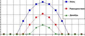
- Compact: The high thermal efficiency of PTs means that they have a very small footprint. For the same heat transfer area, PTs can often occupy 80% less area (sometimes 10 times less) than shell-and-tube heat exchangers (Figure 7).
- Fouling Reduction: Fouling reduction occurs as a result of a combination of high turbulence and short fluid residence time. Correction factors for contamination for heat exchangers can be tens of times lower than for shell-and-tube heat exchangers.
- Easy to Inspect and Clean: Because PHE components can be separated, all parts that are exposed to liquids can be cleaned and inspected. This feature is essential in the food and pharmaceutical industries.
- Easy leak detection: Gaskets have vent holes (Figure 8) that prevent fluids from mixing in the event of a failure, which also makes leak detection easier.
By the way, read this article too: Welded plate heat exchanger (Block)
Figure 7 - Illustration of the typical size difference between a PT and a shell-and-tube heat exchanger for a given heat load
Figure 8 - Ventilation channels in gaskets to detect possible leaks
Flaws
- Temperature and Pressure Limitations: An important limitation of PT is related to plate gaskets. Pressure and temperature exceeding 25 atm and 160 °C respectively are unacceptable as they may cause standard gaskets to leak. However, the gaskets, made from special materials, can withstand temperatures up to 400 °C, and it is possible to weld or solder the plates to each other to work in more severe conditions. This would have the added benefit of increasing operating limits as well as the ability to handle corrosive fluids as it would eliminate the need for gaskets. However, the PT will lose its main advantages of flexibility and ease of cleaning, and the equipment will become more expensive.
- High pressure drop: Due to the corrugated plates and the small flow space between them, the pressure drop due to friction is high, increasing pumping costs. Pressure drop can be reduced by increasing the number of passes per pass and dividing the flow into more channels. This reduces the flow velocity in the channel, hence reducing the coefficient of friction. However, the convective heat transfer coefficient also decreases, which reduces the efficiency of the heat exchanger.
- Phase Change: In special cases, PTs can be used in condensation or evaporation operations, but are not recommended for gases and vapors due to limited space within the channels and pressure limitations.
- Fluid Types: Processing fluids that are highly viscous or contain fibrous material is not recommended due to high pressure drop and flow distribution issues within the PT. Compatibility between the fluid and gasket material should also be considered. Flammable or toxic liquids should be avoided due to the possibility of leakage.
- Leakage: Friction between metal plates can cause wear and small holes that are difficult to detect. As a precaution, it is recommended that the process fluid be pressurized to reduce the risk of contamination if the plate leaks.
MATERIALS FOR THE MANUFACTURE OF HEAT EXCHANGERS
We have looked at the design and operating principle of a plate heat exchanger, then let's look at what materials are used in the manufacture of devices. Only corrugated plates and sealing gaskets are in direct contact with the working environment, so special attention is paid to the choice of material for these elements.
plate with seal
Plates
Most often they are made of steel grades AISI 316 or AISI 304 , which are resistant to certain types of corrosion. Also, steel plates perfectly withstand high pressures in the system, which is important when using a heat exchanger for heating and hot water supply. But when working with aggressive liquids, steel often corrodes. For such cases, devices with plates made of more expensive materials are offered: titanium or Hastelloy alloy . They do not collapse or corrode under the influence of aggressive chemical acids; they are effective when working with high temperatures, as well as at elevated pressures in the system. Another type of material used in the manufacture of plates is copper . Copper plates are common in devices for the food industry. Technological processes associated with heating wort and other products require high heat transfer rates. The pressure in the system is quite low. Copper, having a high rate of thermal conductivity, copes with this task like no other material.
Sealing gaskets
They ensure the tightness of the plate apparatus and also prevent mixing of working media. Gaskets are made of polymer materials that are resistant to certain temperatures and aggressive liquids and substances:
- EPDM – for working with hot water and steam, withstands temperatures up to +160 0C, not suitable for moving fats and acids;
- NITRIL – used in devices working with fats and oils at temperatures up to +135 0C;
- VITON - withstands the action of most chemical acids, the permissible coolant temperature is up to +180 0C.