What is an elevator unit?
An elevator or thermal unit is a device that simultaneously performs the functions of an injection pump.
The main purpose of this design is to increase the pressure in heating networks and increase the pumping and volume of coolant in the main. The heating elevator allows you to transport coolant with a temperature of +150°C along the main line, which increases the energy efficiency of the heating system. If we compare the heat transfer of a certain volume of liquid with a temperature of +90°C with the same volume of liquid with a temperature of 150 degrees, then the amount of transported thermal energy in the second case will be significantly greater.
Describing the elevator unit of the heating system and what it is, it is worth noting that such devices allow you to quickly move coolant with a temperature above the boiling point along the main line without converting the liquid into steam. This is achieved due to the fact that high pressure is constantly maintained in the network.
Scheme and principle of operation
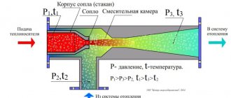
The layout of the elevator heating unit is quite simple. Externally, the design resembles a bulky tee made of metal pipes, each of which has a connecting flange at the end.
A typical diagram of an elevator heating unit looks like this:
- The left pipe resembles a nozzle, which tapers to the required design diameter.
- This is followed by the mixing chamber cylinder.
- At the bottom there is a pipe for connecting the return pipeline.
- There is another pipe on the right side. This is a special diffuser with an expansion that directs the heated coolant into the heating system.
Having examined the structure of the thermal unit elevator, it is worth understanding its connection. The supply line of the centralized heating network is connected to the left branch pipe. A return pipeline is connected to the lower branch pipe. Shut-off valves and coarse strainers are installed on both sides.
Important! The design of the heating unit must be supplemented with temperature sensors, pressure gauges and heat meters. If we consider a heating unit in an apartment building, the operating principle of the device is as follows:
If we consider a heating unit in an apartment building, the operating principle of the device is as follows:
- As the coolant passes through the pipe with the nozzle, its speed increases due to the increased fluid pressure in the line. This allows you to achieve the effect of an injection pump. Thanks to the nozzle, more efficient circulation of liquid in pipelines is ensured.
- When water enters the mixing chamber, the pressure decreases. As the jet passes through the diffuser in the mixing chamber, the medium becomes rarefied. Due to the injection effect, the high-pressure liquid carries with it water from the return line.
- Cooled and heated streams are mixed in the elevator chamber. As a result, when leaving the diffuser, the coolant has a temperature within 95 degrees.
Important! For efficient operation of the elevator unit, the pressure difference in the supply and return lines must be within certain limits in order to overcome the hydraulic resistance of the fluid
Pros and cons of a thermal unit
The elevator unit of the heating system has the following advantages:
- Reasonable cost and simplicity of design make the elevator in demand, despite its impressive age.
- This non-volatile device does not require power supply to operate.
- Thanks to the presence of a heating elevator, the cross-section of the main pipeline can be made smaller, which allows saving on its construction.
The disadvantages of this device are the impossibility of adjusting the temperature of the coolant. However, this drawback can be mitigated by using devices to adjust the nozzle diameter. In this case, control over the temperature is carried out by controlling the flow rate, which affects the degree of vacuum in the mixing chamber.
Common failures of the elevator unit
The main malfunctions of the heating system elevator can be caused by failure of the device itself due to clogging or an increase in the internal diameter of the nozzle. Also, the cause of the breakdown may be a clogged mud trap. breakdown of shut-off valves and failure of regulator settings.
The breakdown of the elevator unit of the heating system can be determined by the temperature difference before and after the device. If a strong difference is detected, it can be stated that the elevator is broken due to clogging or an increase in the diameter of the nozzle. But regardless of the breakdown, diagnostics are carried out by certified specialists. If the elevator unit is clogged, it is cleaned.
If the original diameter has increased due to corrosion, then the entire heating system will be completely unbalanced. In this case, the radiators in the rooms on the top floor will not receive thermal energy in full, and the radiators in the lower apartments will overheat greatly. To eliminate the problem, the nozzle is replaced with a new analogue with the required diameter.
Clogging of the mud traps in the elevator heating unit can be detected by changing the readings of pressure sensors located immediately before and after the device. To remove contaminants in the thermal system, they are discharged using a tap located in the lower part of the sump. If such actions do not give positive results, then the device is dismantled and mechanically cleaned.
How does an elevator work?
In simple terms, an elevator in a heating system is a water pump that does not require external energy. Thanks to this, and even its simple design and low cost, the element found its place in almost all heating points that were built in Soviet times. But for its reliable operation certain conditions are required, as will be discussed below.
To understand the structure of the heating system elevator, you should study the diagram presented in the figure above. The unit is somewhat reminiscent of a regular tee and is installed on the supply pipeline; with its side outlet it is connected to the return line. Only through a simple tee would water from the network pass directly into the return pipeline and directly into the heating system without reducing the temperature, which is unacceptable.
A standard elevator consists of a supply pipe (pre-chamber) with a built-in nozzle of the calculated diameter and a mixing chamber into which cooled coolant is supplied from the return. At the outlet of the assembly, the pipe expands, forming a diffuser. The unit operates as follows:
- coolant from the high-temperature network is directed to the nozzle;
- when passing through a hole of small diameter, the flow speed increases, which is why a rarefaction zone appears behind the nozzle;
- vacuum causes water to be sucked in from the return pipeline;
- the flows are mixed in the chamber and exit into the heating system through a diffuser.
How the described process occurs is clearly shown by the diagram of the elevator unit, where all flows are marked in different colors:
An indispensable condition for stable operation of the unit is that the pressure difference between the supply and return lines of the heating network is greater than the hydraulic resistance of the heating system.
Along with obvious advantages, this mixing unit has one significant drawback. The fact is that the operating principle of the heating elevator does not allow regulating the temperature of the mixture at the outlet. After all, what is needed for this? If necessary, change the amount of superheated coolant from the network and sucked water from the return. For example, in order to reduce the temperature, it is necessary to reduce the supply flow and increase the flow of coolant through the jumper. This can only be achieved by reducing the nozzle diameter, which is impossible.
Electric elevators help solve the problem of quality regulation. In them, by means of a mechanical drive rotated by an electric motor, the diameter of the nozzle increases or decreases. This is achieved through a cone-shaped throttle needle that enters the nozzle from the inside at a certain distance. Below is a diagram of a heating elevator with the ability to control the temperature of the mixture:
1 – nozzle; 2 – throttle needle; 3 – actuator housing with guides; 4 – shaft with gear drive.
Note. The drive shaft can be equipped with either a handle for manual control or an electric motor activated remotely.
The adjustable heating elevator, which appeared relatively recently, allows for the modernization of heating points without a radical replacement of equipment. Considering how many other similar units operate in the CIS, such units are becoming increasingly relevant.
The principle of operation of the elevator
Externally, the design resembles a large tee made of metal pipes with connecting flanges at the ends. How the elevator works inside:
- the left nozzle (see drawing) is a tapering nozzle of the calculated diameter;
- behind the nozzle there is a cylindrical mixing chamber;
- the lower pipe is used to connect the return line to the mixing chamber;
- the right pipe is an expanding diffuser that directs coolant into the heating network of a multi-story building.
In the drawing, the ejected flow pipe is conventionally shown at the top, although it is usually located at the bottom
Note. In the classic version, the elevator does not require connection to the house electrical network. An updated version of the product with an adjustable nozzle and an electric drive is connected to an external power source.
The steel elevator unit is connected by the left branch pipe to the supply line of the centralized heating network, and by the bottom branch pipe to the return pipeline. Shut-off valves are installed on both sides of the element, plus a mesh filter - a sump (otherwise known as a sludge tank) on the supply. The traditional scheme of a heating point with an elevator also includes pressure gauges, thermometers (on both lines) and a meter for energy consumption.
Now let's look at how the elevator jumper works:
- Superheated water from the heating network passes through the left pipe to the nozzle.
- At the moment of passing through the narrow section of the nozzle under high pressure, the flow accelerates according to Bernoulli's law. The effect of a water jet pump begins to operate, ensuring the circulation of coolant in the system.
- In the area of the mixing chamber, the water pressure decreases to normal.
- The jet moving at high speed into the diffuser creates a vacuum in the mixing chamber. An ejection effect occurs - a flow of liquid with a higher pressure entrains the coolant returning from the heating network through the jumper.
- In the heating elevator chamber, the cooled water is mixed with superheated water, and at the outlet of the diffuser we obtain the coolant at the required temperature (up to 95 °C).
Clarification. It is worth noting that the elevator unit also uses the injection principle in its operation - mixing two jets with simultaneous transfer of energy. The pressure of the resulting flow becomes less than the initial one, but more than that sucked from the return. The process is shown more clearly in the video:
The main condition for normal operation of the elevator is a sufficient pressure difference between the main supply and the return line. This difference should be enough to overcome the hydraulic resistance of the home heating system and the injector itself. Please note: the vertical jumper cuts into the return at an angle of 45° for better flow separation.
At the supply from the heating network, the pressure is highest, at the outlet from the diffuser - average, in the return line - the lowest. The same thing happens in the elevator with water temperature
Elevator what is it
To understand and understand what this element is, it is best to go down to the basement of the building and see it with your own eyes. But if you have no desire to leave your home, then you can view the photo and video files in our gallery. In the basement, among the many gate valves, pipelines, pressure gauges and thermometers, you will definitely find this unit.
We suggest first understanding the principle of operation. Hot water is supplied to the building from the district boiler house, and cooled water is discharged.
This requires:
- Supply pipeline
– supplies hot coolant to the consumer; - Return pipeline
- performs the work of removing the cooled coolant and returning it to the district boiler room.
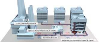
Several houses, and in some cases each one if the houses are large, are equipped with thermal chambers. They distribute coolant between houses, and also install shut-off valves that serve to cut off pipelines. Drainage devices can also be installed in the chambers, which are used to empty pipes, for example, for repair work. Further, the process depends on the temperature of the coolant.
In our country there are several main modes of operation of district boiler houses:
- Supply 150 and return 70 degrees Celsius;
- Respectively 130 and 70;
- 95 and 70.
The choice of mode depends on the latitude of residence. So, for example, for Moscow a 130/70 schedule will be sufficient, but for Irkutsk a 150/70 schedule will be needed. The names of these modes have the numbers of the maximum load of the pipelines. But depending on the air temperature outside the window, the boiler room can operate at temperatures of 70/54.
This is done to prevent overheating in the rooms and to make them comfortable to stay in. This adjustment is performed at the boiler room and is a representative of the central type of adjustment. An interesting fact is that in European countries a different type of regulation is performed - local. That is, adjustment takes place at the heat supply facility itself.
In this case, heating networks and boiler houses operate at maximum capacity. It is worth saying that the highest performance of boiler units is achieved precisely at maximum loads. comes to the consumer and is locally regulated by special mechanisms.
These mechanisms consist of:
- Outdoor and indoor temperature sensors;
- Servo drive;
- Actuator with valve.
Such systems are equipped with individual devices for metering thermal energy, thereby achieving great savings in monetary resources. Compared to elevators, such systems are less reliable and durable.
So, if the coolant has a temperature of no more than 95 degrees, then the main task is the high-quality physical distribution of heat throughout the system. To achieve these goals, manifolds and balancing valves are used.
But in the case when the temperature is above 95 degrees, it needs to be reduced a little. This is what elevators do in the heating system; they add chilled water from the return line to the supply pipeline.
Features and Specifications
As we have already figured out, the elevator of the heating system is responsible for cooling the superheated water to a given value. This prepared water then enters.
This element improves the quality of operation of the entire building system and, when properly installed and selected, performs two functions:
- Mixing;
- Circulation.
Advantages of the elevator heating system:
- Simplicity of design;
- High efficiency;
- No electrical connection required.
Flaws:
- We need accurate and high-quality calculation and selection of a heating elevator;
- There is no way to regulate the outlet temperature;
- It is necessary to maintain a pressure difference between supply and return of around 0.8-2 bar.
Nowadays, such elements have become widespread in heating networks. This is due to their advantages, such as resistance to changes in hydraulic and temperature conditions. In addition, they do not require constant human presence.
Design
The elevator consists of:
- Vacuum chambers;
- Nozzles;
- Jet elevator.
Among heating engineers there is a concept called piping an elevator unit. It consists of installing the necessary shut-off valves, pressure gauges and thermometers. All this is assembled and is a unit.
Advantages and disadvantages
The practicality of the heating elevator is due to the following advantages:
- simplicity of the device and, as a result, minimal maintenance;
- durability;
- low cost;
- energy independence (functions without electricity);
- independence of the mixing coefficient from the hydraulic regime in the external network;
- the presence of an additional function: the unit plays the role of a circulation pump.
The characteristic “disadvantages” of this technology are:
- lack of ability to regulate outlet temperature;
- the need for a pressure difference between the supply and return lines in the range of 0.8 - 2 atm;
- complexity and high accuracy of calculating the diameter of the cone nozzle and the dimensions of the mixing chamber.
How does an elevator unit work?
Before understanding the structure of the elevator unit, we note that this mechanism is intended to connect end-users of heat to heating networks. By design, the thermal elevator unit is a kind of pump that is included in the heating system along with shut-off elements and pressure meters.
The elevator heating unit performs several functions. First of all, it redistributes the pressure inside the heating system so that water is supplied to the end consumers in the radiators at the specified temperature. When passing through pipelines from the boiler room to apartments, the amount of coolant in the circuit almost doubles. This is only possible if there is a supply of water in a separate sealed container.
As a rule, coolant is supplied from the boiler room, the temperature of which reaches 105-150 ℃. Such high rates are unacceptable for domestic purposes from a safety point of view. According to regulatory documents, the maximum water temperature in the circuit cannot exceed 95 ℃.
It is noteworthy that SanPin currently sets the coolant temperature standard within 60 ℃. However, in order to save resources, a proposal to reduce this standard to 50 ℃ is being actively discussed. According to an expert opinion, the difference will not be noticeable to the consumer, and in order to disinfect the coolant, it will need to be heated to 70 ℃ every day. However, these changes to SanPin have not yet been adopted, since there is no clear opinion about the rationality and effectiveness of such a decision.
The diagram of the elevator heating unit allows you to bring the temperature of the coolant in the system to standard values.
This node allows you to avoid the following consequences:
Batteries that are too hot can cause skin burns if handled carelessly; not all heating pipes are designed for prolonged exposure to high temperatures under pressure - such extreme conditions can lead to premature failure; if the wiring is made of metal-plastic or polypropylene pipes, it is not designed for the circulation of hot coolant.
How is the thermal unit arranged?
In general, the technical structure of each heating point is designed separately depending on the specific requirements of the customer. There are several basic schemes for the design of heating points. Let's look at them one by one.
Thermal unit based on an elevator.
The scheme of a heating point based on an elevator unit is the simplest and cheapest. Its main drawback is the inability to regulate the temperature of the coolant in the pipes. This causes inconvenience for the end user and a large overconsumption of thermal energy in the event of thaws during the heating season. Let's look at the figure below and understand how this circuit works:
In addition to what is indicated above, the thermal unit may include a pressure reducer. It is installed on the feed in front of the elevator. The elevator is the main part of this scheme, in which the cooled coolant from the “return” is mixed with the hot coolant from the “supply”. The operating principle of the elevator is based on creating a vacuum at its output. As a result of this vacuum, the coolant pressure in the elevator is less than the coolant pressure in the “return” and mixing occurs.
Thermal unit based on a heat exchanger.
A heating point connected through a special heat exchanger allows you to separate the coolant from the heating main from the coolant inside the house. The separation of coolants allows for its preparation using special additives and filtration. With this scheme, there are ample opportunities to regulate the pressure and temperature of the coolant inside the house. This allows you to reduce heating costs. To have a clear idea of this design, look at the figure below.
The mixing of coolant in such systems is done using thermostatic valves. In such heating systems, in principle, aluminum radiators can be used, but they will last for a long time only if the coolant is of good quality. If the PH of the coolant goes beyond those approved by the manufacturer, then the service life of aluminum radiators may be greatly reduced. You cannot control the quality of the coolant, so it is better to play it safe and install bimetallic or cast iron radiators.
DHW can be connected in a similar way via a heat exchanger. This offers the same benefits in terms of hot water temperature and pressure control. It is worth saying that unscrupulous management companies can deceive consumers by lowering the hot water temperature by a couple of degrees. For the consumer, this is almost unnoticeable, but on a household scale it allows you to save tens of thousands of rubles per month.
Determining the value of the thermal unit
An elevator is a non-volatile independent device that performs the functions of water-jet pumping equipment. The heating unit lowers the pressure and temperature of the coolant by mixing in cooled water from the heating system.
The equipment is capable of transmitting coolant heated to the highest possible temperatures, which is beneficial from an economic point of view. A ton of water heated to +150 C has much greater thermal energy than a ton of coolant with a temperature of only +90 C.
Operating principles and detailed diagram of the thermal unit
To understand how the equipment works, you need to understand its structure. The layout of the elevator heating unit is not complicated. The device is a metal tee with connecting flanges at the ends.
The design features are:
- the left nozzle is a nozzle tapered towards the end to the design diameter;
- Behind the nozzle there is a cylindrical mixing chamber;
- the lower pipe is needed to connect the water return circulation pipeline;
- the right pipe is a diffuser with expansion that transports hot coolant into the network.
Despite the simple design of the thermal unit elevator, the operating principle of the unit is much more complex:
- The coolant heated to a high temperature moves through the pipe into the nozzle, then under pressure the transportation speed increases, and the water quickly flows through the nozzle into the chamber. The effect of a water jet pump maintains a given intensity of coolant flow in the system.
- As water passes through the chamber, the pressure decreases and the stream passes through the diffuser, providing a vacuum in the mixing chamber. Then, under high pressure, the coolant moves the liquid returned from the heating line through the jumper. The pressure is created by the ejection effect due to the vacuum, which maintains the flow of the supplied coolant.
- In the mixing chamber, the temperature regime of the flows decreases to +95 C, this is the optimal indicator for transportation through the home heating system.
Understanding what a heating unit is in an apartment building, the principle of operation of an elevator and its capabilities, it is important to maintain the recommended pressure difference in the supply and return pipelines. The difference is necessary to overcome the hydraulic resistance of the network in the house and the device itself
The elevator unit of the heating system is integrated into the network as follows:
- the left pipe is connected to the supply line;
- lower – to pipes with reverse transportation;
- shut-off valves are mounted on both sides and are supplemented with a dirt filter to prevent clogging of the unit.
The entire circuit is equipped with pressure gauges, heat consumption meters, and thermometers. For better flow resistance, the jumper is cut into the return pipeline at an angle of 45 degrees.
Advantages and disadvantages of thermal units
A non-volatile heating elevator is inexpensive, does not need to be connected to a power supply, and works flawlessly with any type of coolant. These properties ensured the demand for equipment in houses with central heating, where a high degree of heating coolant is supplied.
Disadvantages of use:
- Maintaining the differential water pressure in the return and supply pipelines.
- Each line requires specific calculations and parameters of the heating unit. At the slightest change in liquid temperature, you will have to adjust the nozzle holes and install a new nozzle.
- There is no way to smoothly regulate the intensity and heating of the transported coolant.
Units with adjustable flow area by manual or electric drive of a gear transmission located in the antechamber are offered for sale. But in this case, the device loses its energy independence.
Principles of operation of the elevator unit
You already know a little about the elevator unit of the heating system and what it is. Let's take a closer look at how this device functions. It contains 3 flanges into which the inlet and outlet (return) pipes are inserted, as well as a pipeline through which water goes directly to the heat consumer.
The principle of operation of the elevator is as follows: c: first, heated water from the common line enters the pipe of the device in question.
The principle of operation of the elevator Source 1-teplodom.ru
Since the coolant is under pressure, it moves a little further, passing through a narrow nozzle. In this case, an injection effect or Venturi effect occurs, that is, a vacuum zone is created in the next chamber (receiving chamber). Since this chamber has a reduced pressure, the law of thermodynamics begins to operate and cold water from another pipe begins to be sucked into this part of the elevator assembly. The second pipe is connected to the so-called return pipe.
This is interesting! Venturi's law states that the pressure of a fluid drops as it passes through a narrow part of a pipe. At the same time, Bernoulli's law explains why this happens.
As a result of the above processes, in the next part of the device, which is called the mixing neck, hot and cold water are mixed and the pressure is reduced. After this normal temperature, the liquid is sent directly to the system that heats the house in the winter.
Visually about Venturi's law Source stack.imgur.com
Thus, in addition to reducing the operating parameters of the system, the elevator also performs the function of a pump. One of the most important tasks that an elevator solves is creating the necessary and suitable pressure that can overcome the water resistance of the heating system of the house. To do this, a vertical jumper at the joint is cut at an angle of 450. This contributes to better separation of water flows.
The elevator structure contains other elements that are important and important for heat supply. This device is also equipped with filters and piping, which includes:
- pressure gauges (to monitor system pressure);
- filters (free from dirt);
- thermometers (for temperature control; located in three places of the system);
- valves (needed for access to the inside of the system, as well as for emergency and other work).
Filters used in the elevator can be of two types: dirt-collecting or mesh-magnetic. The former remove the largest debris from the coolant, the latter are responsible for purifying the water that enters home heating radiators and pipes.
Pressure gauges, valves and other elevator fittings Source tildacdn.com
Let's consider why an elevator is needed. This device is used mainly in centralized heating systems, namely where the temperature rises to one hundred and fifty degrees Celsius, the pressure is 6-10 bar. This is necessary in order to:
- equipment operating at high temperatures functioned properly and with a high efficiency;
- deliver sufficiently heated water to areas remote from the boiler room;
- save resources (due to the fact that water heated to a temperature of more than 100°C and having increased pressure contains more thermal energy than colder water, for example, ninety degrees).
See also: Catalog of companies that specialize in engineering systems (heating, water supply, sewerage and others) and related work
Thermal distribution point of the building
Heating engineers recommend using one of three temperature modes for boiler operation. These modes were initially calculated theoretically and underwent many years of practical application. They ensure heat transfer with minimal losses over long distances with maximum efficiency.
Thermal conditions of a boiler room can be defined as the ratio of the supply temperature to the return temperature:
- 150/70 – supply temperature is 150 degrees, and return temperature is 70 degrees.
- 130/70 - water temperature 130 degrees, return temperature 70 degrees;
- 95/70 - water temperature 95 degrees, return temperature - 70 degrees.
In real conditions, the mode is selected for each specific region based on the winter air temperature. It should be noted that high temperatures, especially 150 and 130 degrees, cannot be used for heating premises in order to avoid burns and serious consequences in case of depressurization.
The temperature of the water exceeds the boiling point and it does not boil in the pipelines due to the high pressure. This means that it is necessary to reduce the temperature and pressure and ensure the necessary heat extraction for a particular building. This task is assigned to the elevator unit of the heating system - special heating equipment located in the heat distribution point.
Elevator unit dimensions
Elevators are manufactured in several standard sizes, corresponding to the size and needs of the heating system of a house or apartment building entrance:
Table depending on the elevator number and its size
The elevator is selected based on a combination of various parameters - temperature, pressure in the system, pipeline capacity, connection dimensions, etc. Most devices are selected based on the diameter of the pipes supplying the heating system. It is important to ensure that the diameter of the supply pipelines matches the dimensions of the elevator pipes so that the device does not turn out to be a kind of diaphragm that reduces the throughput and pressure in the system. In addition, the performance of the nozzle is affected by the size of the nozzle, which must be carefully calculated. Calculation formulas are available online, but it is not recommended to do it yourself without experience and training. The easiest way is to use an online calculator, which can be found on the Internet. It is advisable to check the result obtained on another calculator to get a more correct result.
Principle and scheme of operation
Scheme and principle of operation
The elevator helps cool superheated water to a temperature that corresponds to the norm.
The coolant then supplies it to the residential heating system. At the moment when hot water in the elevator from the supply heat pipe is mixed with cooled water from the return pipe, cooling occurs.
The layout of the elevator allows you to become more familiar with its functionality. It is not difficult to understand that it is this part of the heating system that ensures the efficiency of its operation.
It works simultaneously as 2 devices:
- Circulation pump
- Mixer
The design of the elevator is quite simple, but effective. It has a reasonable price. No electrical current is required for it to work.
However, there are some disadvantages that need to be taken into account:
- The pressure in the forward and reverse transmission pipelines must be maintained within 0.8-2 Bar;
- The outlet temperature cannot be adjusted;
- Each element of the elevator must be precisely calculated.
It is safe to say that the devices are widely used in the municipal heating system.
Elevator schematic diagram
The efficiency of their operation is not affected by fluctuations in thermal and hydraulic conditions in heating networks. In addition, the devices do not require constant monitoring. By selecting the correct nozzle diameter, all adjustments are made.
Basic elements of the elevator
Basic elements of a node
The main components of the device are:
- Jet elevator
- Nozzle
- Vacuum chamber
The elevator heating unit consists of shut-off valves, control thermometers, and pressure gauges. It is also called “elevator harness”.
New technical ideas and inventions are rapidly being introduced into our lives. District heating is no exception.
The usual elevator units are being replaced by devices that regulate the coolant automatically.
Their cost is much higher, but at the same time, these devices are more economical and energy efficient. In addition, they require power to operate. Sometimes more power is needed. Reliability on the one hand and technical progress on the other.
What will ultimately turn out to be more important, we will find out over time.
Operating principle of the thermal unit circuit
Let's look at the schematic diagram of the elevator unit - that is, the diagram of its operation:
- hot coolant is supplied from the boiler room through the main pipeline to the entrance to the nozzle;
- moving through small cross-section pipes, the water gradually picks up speed;
- in this case, a somewhat discharged area is formed;
- the resulting vacuum begins to suck water from the return;
- homogeneous turbulent flows through the diffuser flow to the outlet.
If the heating system uses a heating unit diagram for an apartment building, then its effective operation can only be ensured if the operating pressure between the supply and return flows is greater than the calculated hydraulic resistance.
How does a heating unit with an elevator mixing unit work?
Elevator mixing units are installed in heating points of buildings that are connected to a heating network operating in a mode with high-quality regulation on “superheated” water.
Qualitative regulation involves changing the temperature of the water entering the heating system depending on the temperature of the outside air, with a constant flow of water circulating in it.
"Overheated"
water is considered if it comes from the heating network at a temperature higher than that required for supply to the heating system.
For example, a heating network can operate on a schedule of 150/70, 130/70 or 110/70, and a heating system is designed on a schedule of 95/70. The temperature graph 150/70 assumes that at the design temperature of the outside air (for Kiev this is -22°C), the temperature at the entrance of the heating networks into the house should be equal to 150°C, and it should go into the heating network at a temperature of 70°C, while This water should enter a house designed for a 95/70 schedule at a temperature of 95°C.
The elevator unit mixes the water flow from the heating network supply with a temperature of 150°C and the water flow leaving the heating system with a temperature of 70°C; as a result of mixing, a flow with a temperature of 95°C is obtained at the elevator outlet, which is supplied to the heating system.
How does mixing occur?
In the mixing chamber of the elevator unit there is a “nozzle/cone” confuser that accelerates the flow of superheated water. As the flow speed increases, the pressure in it decreases (this property is described by Bernoulli's law) so much that it becomes slightly lower than the pressure in the return pipeline. The pressure difference between the mixing chamber and the return pipeline leads to the flow of coolant through the “elevator boot” jumper from the return to the supply.
In the mixing chamber, a mixture of two streams is formed with the required temperature, but the pressure is lower than the pressure of the return pipeline. The mixture enters the elevator diffuser, in which the flow rate decreases and the pressure increases above the return pipeline pressure. The pressure increase is no more than 1.5 m.w.c., which imposes restrictions on elevator units for use in heating systems with high hydraulic resistance.
1 Cheap and easy
2 Maintenance free
3 Does not depend on the electrical network
Disadvantages of elevator mixing units
1 Not compatible with automatic regulators, therefore their joint installation is prohibited by law.
2 Creates an available pressure at the input to the heating system of no more than 1.5 m of water column, which excludes the installation of elevator heating units in buildings whose heating systems are equipped with radiator thermostatic valves.
3 The elevator unit has a constant mixing coefficient, which does not allow supplying coolant of the required temperature to the heating system if the heating network is underheated.
4 Too high sensitivity to the available pressure at the input of the heating network. A decrease in the available pressure relative to the calculated value leads to a decrease in the volumetric flow rate of water circulating in the heating system, which in turn leads to an imbalance of the system and stopping of distant risers/branches.
5 For the elevator to operate, the pressure difference between the supply and return pipelines must exceed 15 m.w.c.
Where are heating points with elevator units installed?
Almost all heating systems put into operation before 2000 are equipped with heating points with elevator units.
Where can elevator ITPs be used?
Currently, for all designed and reconstructed residential and administrative buildings, the use of automatic control at the heating point is mandatory. The use of elevator units in conjunction with automatic regulators is prohibited by regulation.
Elevator units can be installed only in facilities where there is no need for automatic control of the heating system, the available pressure (pressure difference between the supply and return pipelines) at the inlet is stable and exceeds 15 m.w.st., for the operation of the connected heating system, the pressure difference between the supply and return is sufficient return to 1.5 m.water column, and the heating system operates with a constant flow rate and is not equipped with automatic regulators.
Calculation of the throttle washer hole diameter
Calculating the holes of throttle washers is a very important undertaking; it is carried out in accordance with the requirements of SP 41.101/95 for the design of heating stations. The calculation is not difficult for engineering and technical personnel of heating networks and is performed on the basis of one formula. The difficulty lies in the correctness of obtaining accurate data for the calculation formula, which in practice very often do not correspond to the design values, which is why the design diameter is determined incorrectly, and the washer is not able to establish the required hydraulic and thermal operating conditions.
The throttle washer in the heating system is very often changed or a larger flow area is drilled. This work is usually carried out by service technicians during commissioning tests in main heating networks. The calculation is made either manually or using online calculators. Both calculation methods are based on the same formula and use the same input data.
Formula method
Hole diameter D, mm, is calculated by the formula:
Formula for calculating the washer D=10x ∜Р/ ΔН
Where:
- P is the determined flow rate of the heating coolant at maximum temperatures in the supply/return pipeline, t/h;
- ΔН is the pressure that the diaphragm can absorb, m.v.st.
According to the requirements of the regulatory materials SNIP for heating, a limit value for the diameter of the washer hole is established, which cannot be less than 3.0 mm. This is due to the fact that holes that are below the established limit can become clogged with small suspended substances, for example, pieces of rust flying off the inner surface of the pipes, after which the heating system in the house will not work, and to replace such a washer you will have to drain all the water from the network .
In this formula, water consumption P, t/h is taken from the corresponding section of the heat supply project or based on materials from commissioning testing of main heating networks. The consumer can take such data from the contract for heat supply services, since they are prescribed in the relevant sections of such a document.
ΔН – throttled pressure in the washer measured in m.v. Art. This indicator is established as the difference between the available pressure or pressure difference between the supply and return pipelines, installed using pressure gauges in the consumer's subscriber input, and the hydraulic resistance of the in-house heating pipes. Hydraulic resistance is equal to the sum of all pressure losses in the system under consideration. As a rule, it ranges from 0.6 to 2.0 m.v. Art. These hydraulic losses can be taken from the heat supply project in the section hydraulic calculation of heating networks.
In order to perform the calculation correctly, you will need to take into account the recommendations of SNIP:
- When switching on the heating system of a house without an elevator, the available pressure must be at least 6.0 m of water. Art.
- When calculating the throttle hole of the washer, the size of the calculated hydraulic losses in the local heating system is taken at the rate of 1-2 m of water. Art.
- If it is necessary to determine the diameter of the washer for installation in front of the boiler, the size of the calculated hydraulic losses in such a water heater is taken in the range of 1.5 - 2.0 m of water. Art.
- The maximum pressure that must be extinguished at the washer cannot exceed 40.0 m of water. Art.
- The resulting calculated diameter of the washer's throttle hole must be greater than the diameter of the calculated nozzle of the elevator unit.
- Hydraulic losses at the elevator nozzle are assumed to be 40 m.v.st.
Examples of determining the pressure drop for calculating the throttle washer:
- The intra-house network, connected through an elevator node, has an available pressure at the end point of the site of 63.0 m.v. Art. To determine the calculated difference, 40 m.w.st. is reserved for the operation of the elevator unit, 1.m.w.st. for the operation of the local heating system, as a result, the washer will have: 63 - 40- 1 = 22.0 m.w.st., which is more minimum threshold for the washer – 6.0 m.v.st.
- The intra-house network, connected to a thermal chamber without an elevator unit, has an available pressure at the end point of the site of 31.0 m.v. Art. To determine the calculated difference, 2.m.w.st is reserved for the operation of the local heating system, as a result, the washer will have: 31 - 2= 29.0 m.w.st., which is more than the minimum threshold for the washer - 6.0 m.w.st.
Software method
Calculations of throttle washers for a heating system, especially if they need to be made in large quantities, are best performed using the “Hydraulic calculation of pipelines” program online. This calculation is performed more accurately, since it takes into account the KMR - local resistance coefficient. Values are assigned to components installed in water and heat supply systems in which hydraulic resistance occurs caused by deformation of the flow of the liquid medium. The area where the deformation process occurs is called local resistance.
There is a relationship between hydraulic resistance, diameter and CMR:
N=KMSx V/2x g
Where:
- N – medium pressure loss, m.v.st.;
- V – speed of movement of the medium, m/sec;
- g – 9.8 m/sec.
Formula via calculation using KMS
Algorithm for calculating the washer using the program:
- Open the “throttle washer” program tab;
- enter data on the internal diameter of the pipeline, D1 mm;
- enter the value of the internal diameter of the washer, D2 mm;
- enter the value of the KMS obtained earlier on the “resistance calculation” tab;
- press the “get result” button;
- We check the result for compliance with the acceptable calculation parameters and press the “check” button.
- The calculation is considered acceptable if, when checking the KMS, it does not exceed the pressure loss established for the local network at 2.m.v.st.
Ideally, you can calculate and install the washer on a separate residential building, but, as a rule, this will not work well, since intra-block networks simultaneously connect dozens and even hundreds of subscribers who influence each other. Therefore, it makes sense to carry out the calculation and installation of washers only for everyone and taking into account the technical characteristics of each subscriber input of the heating network. Such complex work can only be performed by specialized organizations with sufficient experience, appropriate equipment and software.
Data collection and preliminary calculations
Performing a calculation of throttling washers for a group of consumers according to options for connected thermal power implies collecting more detailed information about each consumer input than with a conventional hydraulic calculation. In addition, an adjustment must be made according to projected calculations for the next 5 years. It is practically difficult to find identical elevator units among consumers, which means that each of them will have its own hydraulic pressure losses. Thus, even with the same theoretical coolant flow rates and flow rates, the internal calculated throttle diameters will be different for each house. Therefore, in order to perform the calculation efficiently, you will need a serious database of heat consumers.
Stages of collecting information for calculating throttle washers:
- Carrying out an inspection of the main pipes of the heating network in the subscriber's heating unit, recording the characteristics and availability of installed equipment.
- Determine the actual pressure resistance on: elevators, valves, bends, mud traps, vents and control devices.
- An as-built diagram of the subscriber heating point is drawn up, indicating the diameters of the pipes, their length and the location of the fittings.
- They check the energy efficiency of the facility and the presence of excess heat losses through structural elements.
- They collect information on the quality of heat supply for individual risers, with apartment-by-apartment clarification of data on the internal air temperature at the calculated winter outdoor temperature. Draw up a diagram of warm and cold apartments.
- They analyze the factors of poor-quality functioning of the heating system and identify problematic risers in a residential building.
The calculation of limiting devices is performed on a hydraulic model of a heating network section, calibrated in the operating thermal mode. As a result of this calculation, analytical materials are prepared that contain all the necessary information about the hydraulic parameters of consumer inputs and the indicators of the main heating networks from the boiler house or central heating point. Based on these data, a final document is being prepared with the calculated design characteristics of limiting devices - main and retaining diaphragms by type of connected thermal load. Recommendations are also being developed to normalize the performance of subscriber input.
Stages of work execution
After completing all calculations and developing recommendations for installing limit washers, the installation of throttling devices begins directly. On in-house heating systems, limiting devices can be installed both during the heating season and during the warm season. This is explained by the fact that normally functioning intra-house heating networks can be disconnected by inlet valves on the supply/return pipeline from the main network. Installation of washers on intra-block heating networks is carried out only in the summer, before they are filled with coolant. The functionality of the installed devices is checked at the beginning of the heating period, during commissioning.
The key indicators of the accuracy of calculation of limiting devices in the heating system are:
- Correspondence of actual coolant flow rates to design values in supply/return pipelines, in house risers and in individual heating devices. These data can be determined both by the indicators of the counting devices installed at the input of heat meters into the house, and by calculation. The calculation option is based on measurements of 3 thermometer indicators: hot water at the inlet/outlet of the subscriber node, in individual in-house risers and heating devices, as well as the ambient air temperature in the apartment.
- A sign that the heating network is set up correctly is the coefficient of comparative coolant flow, which must be in the range of 0.9 – 1.15, provided that the calculated indicator is taken as one.
- The actual ambient temperature in the room is identical to the design or sanitary standards. Average measured temperatures cannot be lower than calculated temperatures by more than 1 C.
- After completing the process of installing new washers or monitoring old devices for operability and sufficiency in diameter, it is necessary to monitor the ambient temperature level in at least 30% of the premises.
- If, when performing the above points, apartments with low air temperatures are detected or the actual coolant flow does not correspond to the parameter 0.9 - 1.15, it will be necessary to change the throttle diaphragms, as well as reconfigure the automatic temperature controllers.
The final results of the commissioning tests are entered into the thermal passport of the heating system of the house, and upon completion of the work it is formalized in an act to which the following documents are attached:
- Calculation and analytical materials.
- Places for installing the washer and their characteristics.
- Test results of the heating system after installed throttle washers.
- Analysis of the steady-state thermal regime after completion of the washering of the intra-house heating system.
- Correction of washer dimensions in areas where the required temperature conditions have not been achieved.
- Removal of restrictive devices that require adjustment.
What is an elevator unit of a heating system
Trunk heating networks operate in three main modes:
- 95°/70°
- 130°/70°
- 150°/70°
The first number indicates the temperature of the coolant in the forward pipeline, the second – in the return. The coolant is transported over considerable distances, so the temperature is set taking into account the loss of thermal energy during movement and adjusted for climatic or weather conditions. Hence there are three options for supplying coolant - if you constantly heat water to the maximum value, fuel consumption will increase, so heating modes change depending on external conditions.
According to sanitary standards and technical characteristics of household heating equipment, the upper limit of coolant temperature should not exceed 95°. If the water is heated to 130° or 150°, it must be cooled to the set value. There are several reasons for this:
- Most heating devices are not able to work with overheated water - cast iron radiators become brittle, aluminum radiators may fail or cease to maintain system pressure.
- The pipelines used to supply coolant in apartments also have a temperature limit; for example, for plastic pipes a temperature threshold of 90° is set.
- Heating appliances that are too hot are dangerous for people, especially children.
Superheated water does not turn into steam only because there is no such possibility inside the pipelines. It requires the absence of pressure and the presence of free space, which cannot exist in a pipe. Temperature losses during transportation somewhat change the thermal regime of the coolant, but the need to cool it to operating values remains. The issue is resolved by mixing cooled water from the return line until a set temperature is obtained, suitable for use in heating appliances. Mixing of water occurs in special mechanical devices - elevators. They operate in an environment of related elements called the elevator environment, and the entire mixing unit is called the elevator unit.
Calculation of the elevator unit
To calculate the elevator unit, first calculate the diameter of the mixing chamber and select the corresponding elevator number. After this, the diameter of the working nozzle is calculated.
The following formulas are useful for calculations:
The cross section of the injection chamber is calculated in centimeters. To determine this number, you need to know the flow of heated coolant in the network, taking into account hydraulic resistance.
Preparing water for the heating system and how to soften it correctly
This value can be found using the formula given in the table, where:
- Q is the volume of thermal energy, measured in kcal/h, spent on heating the entire structure;
- Tcm is the temperature of the coolant in the outlet pipe after the elevator tee;
- T2о – return temperature;
- h is the resistance of the water column of the liquid, which is measured in meters (this indicator is taken into account in the wiring of the entire circuit, including radiators).
The diameter of the narrow part of the nozzle is calculated using a separate formula. To do this, you need to know the dimensions of the injection chamber in centimeters and the mixing coefficient. The injection coefficient is found using a separate formula. To calculate, we need the temperature of the coolant at the inlet pipe.
Once we know the pressure in the pipeline coming from the centralized heating main, we can calculate the diameter of the nozzle. To do this, the necessary system parameters are converted to centimeters.
After carrying out the calculations, we obtain the necessary data, on the basis of which we can select a suitable model of the elevator unit and determine the conditions for its correct and uninterrupted operation. In other words, we can determine the required system performance by knowing the volume of circulating coolant that is pumped through the elevator per unit of time, as well as the minimum liquid pressure. The main parameters when choosing a suitable device model are the cross-section of the mixing chamber neck and the elevator nozzle.
Important! We round the nozzle diameter down to hundredths of a millimeter. But the minimum value cannot be less than three millimeters, because the nozzle will quickly become clogged.
Operating principle of the elevator unit
The operating principle of a thermal elevator unit and a water-jet elevator. In the previous article, we found out the main purpose of the thermal elevator unit and the operating features of water-jet or, as they are also called, injection elevators. In short, the main purpose of the elevator is to lower the water temperature and at the same time increase the volume of pumped water in the internal heating system of a residential building.
Now let’s look at how a water jet elevator actually works and how it increases the pumping of coolant through the radiators in the apartment.
The coolant enters the house at a temperature corresponding to the temperature schedule of the boiler room. The temperature graph is the relationship between the temperature outside and the temperature that the boiler house or thermal power plant must supply to the heating network, and accordingly, with small losses, to your heating point (water, moving through pipes over long distances, cools down a little). The colder it is outside, the higher the temperature the boiler room produces.
For example, with a temperature chart of 130/70:
- at +8 degrees outside, the heating supply pipe should be 42 degrees;
- at 0 degrees 76 degrees;
- at -22 degrees 115 degrees;
If anyone is interested in more detailed figures, you can download temperature graphs for various heating systems here.
What is a “heating network” and a “heating unit”
The home heating network is a set of pipelines that provide heat to each living space. This is a complex system that consists of two heat pipes: hot and cooled.
Thermal unit – heating equipment system; the place where the hot water pipe merges with the heating system of the building. This is where heat distribution and metering takes place.
The list of tasks performed includes:
- monitoring the condition of the heat source;
- monitoring the condition of water and heat pipelines;
- registration of data from metering devices.
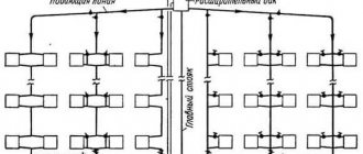
Types of heating units
In multi-storey buildings, two types of heating units are used.
Single-circuit provides a direct connection to hot water supply pipes, that is, the heat pipes are connected using an elevator. In high-rise buildings, the heating network is quite extensive, but most of the equipment is located in the basement.
Important! The diagram of a double-circuit heating unit is a system of two heat pipes in contact with each other through a heat exchanger.
Next, we will consider in more detail the principle of operation of a single-circuit thermal unit. Due to its design, namely the presence of an elevator, and low cost, it is used most often. For companies that install heating equipment and heating units, it is more profitable to use elevator units that are outdated and do not require careful attention.
Device
The single-circuit thermal unit is designed most simply. As already mentioned, it consists of a pipe extending from the heat source and a “cold” pipe, which are connected using an elevator. Also on the pipes there are filters and measuring instruments that monitor the flow, temperature of the coolant and pressure in the pipes.
Filtration equipment is installed, since the entire heating system reacts quite negatively to dirt and sediment in the coolant. Over time, it needs to be cleaned or replaced.
Important! If the pressure is unstable, a device is installed in the heating unit to reduce it.
Installing meters has some nuances:
- placed on a pipe with “reverse” heat;
- it must be located as close as possible, as realistically as possible, to the heat source;
- setting parameters (required amount of heat per hour, day).
Operating principle
In this paragraph we will tell you what processes occur inside the elevator heating unit.
According to the scheme, hot water supplied by utilities enters the house through a “hot” pipe. Having “bypassed” the entire building, it returns to the node in a cooled state and is removed from the system. But in the elevator, hot and “cold” water are mixed, preventing the temperature from going beyond acceptable limits. There are situations (suitable for areas with low temperatures) where a heating mechanism is built into the elevator: if the temperature of the water during mixing is below the permissible level, the mechanism is turned on.
The in-house heating system can be disconnected from the city heating system using valves. Such actions are carried out during repair work and for general prevention. For such cases, there are special valves on the pipes designed to remove water from the system.
Important! All parts of the unit are connected to the heating system using flange connections.
The use of a single-circuit unit has both advantages and disadvantages.
The advantages of such a heating unit are:
- ease of use;
- rare breakdowns;
- relative cheapness of components and their installation;
- completely mechanized and does not depend on external energy sources.
The main negative aspects:
- for each heat pipeline, personal calculations of parameters are required to select an elevator;
- the pressure in each pipe should be different;
- manual adjustment only;
- Who installs and maintains the heating unit.
In houses with a large number of apartments there is a heat and hot water supply system from the city, which is located in the basement. Such a heating system requires preventive maintenance. The “weakest link” is the filters, or mud collectors, which need to be monitored and cleaned (all the dirt from the coolant accumulates in them).
This work is done, or at least should be done, by mechanics from the housing and communal services authorities who service the building. Since the heating center is complex and dangerous to operate, intervention by strangers is under no circumstances allowed, and diagnostics and repairs are allowed only to specially trained personnel.