What is it and why is it needed?
A bypass valve, also known as an overflow valve, is a device that regulates the pressure in the system by bypassing or draining an excess volume of the working medium (gaseous or liquid) into another circuit. The peculiarity of the unit is that it is capable of doing this continuously, which differs from its safety analogue, which reduces the pressure in the pipeline by one-time or periodically removing the medium from it.
A similar pressure reducer, in contrast to the overflow unit, maintains a stable pressure of liquid in the flow following from it, while the overflow unit maintains a stable pressure before itself.
What is the purpose of a bypass valve in a pipeline?
During operation of heating or water heating systems, the volume of the working medium may change. An increase or decrease in coolant pressure negatively affects the performance of the heating circuit: it can lead to uneven heating, airing of system components, and breakdowns. A change in the pressure of the working environment also affects comfort: the temperature in the rooms changes uncontrollably, and the pipes begin to hum and vibrate. To prevent this from happening, it is important to maintain a pressure balance in the pipeline.
It is not difficult to constantly monitor the pressure, bleed or add coolant manually, but it is better to entrust this routine work to automation.
There are several types of control valves that cope with this task better than a person.
The bypass, or overflow, valve allows you to stabilize the pressure in the pipeline by redirecting the working fluid through an additional branch of the pipeline, called a bypass.
Regulation does not occur by one-time or periodic bleeding of excess coolant, but in portions, due to which the pressure of the liquid or gas is constantly maintained at the same level.
Note! The bypass valve controls the pressure automatically, does not require human intervention and, unlike manual adjustment, does not air the system.
The device can and should be equipped with pipelines of any complexity, but most of all they need pressure adjustment:
- multi-circuit heating systems - if one of the circuits is turned off, coolant consumption decreases and pressure increases, which can cause pipeline breaks, overload the pump and heat-generating device - to avoid this, you need to reduce the pressure and maintain it at the required level;
- heating systems equipped with thermostats and hot water supply systems - when setting the temperature, the volume of coolant consumed changes, and it is necessary to quickly restore the pressure balance in the circuit;
- water supply systems equipped with storage-type water heaters - in the boiler and pipeline the water is under high pressure, and since the volume of supplied liquid changes jerkily due to constant adjustment and frequent turning on and off of water, it is especially important to regulate the pressure of the working medium so that an accident does not occur and The water heater is broken.
We recommend that you read: Features of the production and use of ceramic sewer pipes
Areas of use
The valve is used in pipelines where increased pressure of the working medium may occur.
In cars, it dumps excess exhaust gases that spin the turbine blades, thereby reducing the pressure in the intake manifold. This ultimately protects the engine from overheating and failure. In the fuel supply and cooling lines, it drains the excess generated under pressure into the fuel tank and expansion tank, respectively.
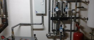
This fitting is widely used in heating and hot water supply devices, where it ensures the rational functioning of all heating devices and pipeline sections. In combination with balancing and other valves, the fittings act as a pressure regulator.
Installation
The valve is installed in accordance with the installation instructions. Tips for proper installation of different types of automation:
- a strainer is installed in front of the overflow valve;
- pressure gauges are installed before and after the valve;
- the device is embedded so that its body does not experience mechanical loads of torsion, compression or tension associated with the operation of the connected circuit;
- It is better to select and install automation with the organization of straight sections in front of the valve (5DN) and after it (10DN);
- the overflow device is mounted on pipes located horizontally, inclined or vertical, unless the instructions contain other instructions in this regard.
The automation is configured after water is released into the main during the setup of the entire unit. It is possible to adjust the valve in an empty pipeline if there is an acceptable value.
The autovalve is regulated by creating the required differential at the location of the device; the screw is rotated until the valve opens. The difference is reduced and the moment of closing the damper is monitored, and the device is additionally adjusted. The pressure changes smoothly due to the fact that each revolution of the screw corresponds to a clear range of pressure changes.
The operation of the valve is checked by changing the pressure drop at the installation site. The accuracy of adjustment and the speed of opening of the damper are checked. The error is allowed within 10% at the limit values. The set pressure corresponds to the opening moment; full expansion is achieved at values of higher pressure drop.
Maintenance is done once a month, the setting pressure indicator and the speed at which the damper begins to open are checked. The operation of the bypass valve is checked by changing the pressure at its location. The filter is cleaned depending on the degree of contamination, as evidenced by pressure gauge readings.
Mechanism
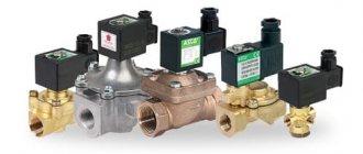
The design includes a metal body (cast iron, bronze, brass), inside of which there is a damper and a spring that activates it. The valve can be a spool valve, a plate, etc. Another option is a shut-off membrane with a rod. A handle is built into the body, which is used to adjust the device.
Devices used in large networks and large-diameter pipelines may contain a lever-load mechanism in their housing.
Bypass valve design:
Operating principle of the heating system bypass valve
The bypass valve is connected to:
- pump;
- return pipe;
- supply pipe.
The operating principle of the heating system bypass valve differs from the safety valve, so they should not be identified. They are connected in different ways, the safety one is mounted to the waste pipe.
When the radiators are closed under the influence of thermostats, the pressure in the heating system increases and the bypass valve is turned on, which transfers the hot liquid to the return line.
The rapid operation of the bypass valve also reduces the pressure in the heating circuit and makes it more stable, which significantly reduces the risks for water radiators.
If we are talking about more complex heating systems, where there are several circuits, then in such cases the bypass valve is mounted behind all the circulation pumps that are present in the system. If bypass valves are installed in such systems, the heating circuits operate stably and without failures in normal mode.
In heating systems, the circulation pump is followed by a check valve, which acts as a kind of obstacle to the coolant and does not allow it to move in the opposite direction due to increased pressure.
The design of the check valve consists of a damper and a spring with a small force, which is quite enough to block the passage for the coolant, the movement of which can go in the opposite direction.
Principle of operation
The coolant, water, and gaseous medium, moving through the pipeline, exert pressure on the valve, which is held in place by a spring. As soon as the pressure force reaches a predetermined level, the valve opens and the excess volume of the working medium is discharged through a special branch into another circuit of the system.
After the level drops to normal, the spiral returns the valve to its original position and the contents of the pipeline continue to circulate.
With a membrane mechanism, the passage for the coolant under the influence of pressure is opened by the membrane. When the pressure returns to normal, the membrane returns to its original place.
In a car, the turbine bypass assembly has a damper, the full opening or closing of which depends on the activator lever. The length of its pull can change over time under the influence of various factors. Therefore, this is monitored and the traction is adjusted.
Difference from other control devices
A bypass valve is often confused with a safety valve and a pressure relief valve. However, despite the general similarity in appearance and functions performed by these devices, there are differences in the mechanism of pressure reduction and the frequency of action.
| Device type | Pressure reduction mechanism | Frequency of action |
| bypass valve | excess working medium is diverted into an additional branch of the pipeline, the pressure of the liquid or gas passing through the main branch is regulated, while the valve is located on the additional | constantly as long as necessary |
| safety valve | excess coolant is released into the external environment or sewerage by opening the valve | occasionally due to pressure changes |
| pressure reducing valve (pressure reducer) | installed on the main branch and regulates the pressure of the working medium by decreasing and increasing its throughput, controls the pressure in the part of the pipeline located after the device | constantly |
We recommend that you read: Crab fastening - connection system for profile pipes
Types and designs
According to the operating principles, bypass valves are distinguished with spring and membrane designs. Spring mechanisms prevail in systems where the pipeline cross-section is no more than 200 mm; in other water supply and heating networks, the lever-load principle is used.
Membrane units are increasingly used when working with liquid media that contain solid particles.
Depending on the pipeline environment, bypass devices are intended for:
- gas;
- pair;
- liquids.
According to the purpose of the system, they are used for pipelines:
- cold water supply,
- hot water supply,
- heating,
- cooling,
- conditioning.
In heating and water supply systems, bypass valves are distinguished according to their purpose:
- for radiators;
- for boiler and bypass;
- for automatic replenishment;
- for low or high pressures.
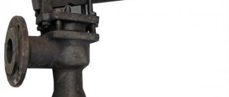
This photo shows an overflow valve with a setting scale. Made of bronze and brass, designed for installation in central heating systems.
Along with bypass regulators, the following is installed in the heating design:
- air vent to prevent air locks in pipes;
- three-way valve for mixing or separating hot and cold water flows;
- reverse, preventing backflow in the pipeline.
For industrial and utility networks, designs with a nominal diameter DN of up to 500 mm and a flange connection are used.
In the car there are access devices for:
- turbines;
- fuel supply mechanism;
- engine cooling systems.
The turbine bypass unit discharges the exhaust gases, reducing the pressure force in the manifold. Thus, it protects the engine from overheating.
In the fuel pipeline, the overflow unit regulates the rate of gasoline supply in it by draining the excess pumped to the engine by the gasoline pump back into the fuel tank.
How to choose a valve for a boiler and bypass
In the factory configuration, boilers and bypasses are either equipped with the simplest bypass valve or do not have a device for redirecting the flow.
In the first case, you can not interfere with the design of the water heater or bypass element and install them in their existing form.
In the second case, it is necessary to purchase and install bypass valves. A bypass without this device will only allow the flow of the working medium to pass when the heating circuit is turned off, but will not be able to regulate the pressure. A boiler that is not equipped with a bypass valve is susceptible to overheating and may break down, since the water in it will boil and turn into steam, further increasing the pressure on the pipes and the heating unit itself.
The choice of device depends on the heating or water heating device: the fuel it uses, the maximum permissible pressure specified in the technical documentation.
Note! It is also important to consider your own capabilities to manage the pressure regulation process - whether you have the skills to configure the operating parameters of the bypass valve.
The price of the product in this matter can only play a role when choosing between similar devices from different manufacturers.
We recommend that you read: Which ball valves are best for water supply
Different types of heating devices require valves of different designs:
- Systems running on electricity, gas or diesel fuel are undemanding - to regulate the pressure in them, a simple bypass valve that does not have additional elements is sufficient.
- Solid fuel does not stop burning immediately, therefore it is impossible to immediately turn off the solid fuel boiler or smoothly adjust the heating temperature. Therefore, in solid fuel heating systems it is important not only to regulate the pressure, but also to cool the heat-generating unit. Bypass valves are installed on bypasses and boilers, which respond to both an increase in pressure and an increase in the temperature of the coolant. Such devices are equipped with a temperature sensor, a coolant discharge and replenishment system and are connected to a sewerage system and a cold water supply system.
- A bypass valve with a control handle should only be installed if the homeowner already knows how to set the pressure limit. If you try to acquire this skill in practice, you can break the device, cause an accident, or get burned.
- For open-type thermal circuits, bypass valves are not required - the compensation tank copes with the task of regulating pressure without them.
- The technical characteristics of the bypass valve must correspond to the parameters of the heat source: the control valves must be set to the same maximum pressure as the heat-generating device and have a flow capacity no lower. It is also important to match the dimensions of the connecting pipes - if this condition is not met, you will have to use fittings for connection, which will make the system more vulnerable.
Specifications
Each bypass valve is characterized by several parameters, which should also be taken into account when choosing a product:
| Characteristic name | What does it mean |
| throughput | volume of coolant consumed per unit time at unit pressure |
| nominal pressure | maximum excess pressure of the working environment, maintained at 200 degrees |
| nominal diameter | the internal cross-section of the connecting pipes may have a slight deviation from the actual size |
| setting range | limits of the maximum pressure adjustable on the valve |
Selection tips and approximate prices
When choosing a bypass device, the consumer must be aware that it is designed to ensure normal operation of the system and constantly maintain stable pressure inside it.
Such a device must meet the following requirements:
- help reduce pressure, quickly redirect excess coolant volume to another circuit;
- have a sufficient range of adjustment;
- be suitable for the method of connection to pipes, for example, have a threaded connection for pipes with a diameter of ½′′.
The throughput device is selected, first of all, based on the type of working medium of the pipeline: gas, steam, water.
Next, they are guided by certain criteria.
Criteria
The main ones are:
- features of the actuator;
- pipeline type and configuration;
- valve material;
- device diameter (DN), which should not be less than the cross-section of the supply pipe;
- range of pressure drops supported by the device;
- damper capacity, characterized by maximum and minimum Kvs values;
- operating and maximum media temperature.
The specific operating pressure to which the valve must be adjusted is specified in the data sheet.
It is important to provide for correct installation, for which everything must be correctly calculated taking into account the parameters and configuration of the system. For example, in a complex heating structure, it is better to install an overflow regulator behind all pumps, and additionally use check valves to protect them.
You should pay attention to the reliability of suppliers so as not to run into counterfeit products.
The approximate price for bypass valves for domestic use varies from 1,700 to 5,200 rubles. Industrial designs equipped with measuring instruments, flanges, and a wide range of settings are much more expensive.
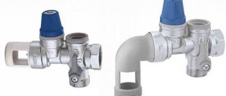
Thus, the overflow angle valve shown in the photo with DN ¾”, designed for 0.06-0.36 bar, with an adjusting head, will cost 1,680 rubles. It is installed to ensure normal operation of the pump. Drains excess coolant when the pressure in the radiators is exceeded into the return line.
If you have to purchase a bypass device for a car, you must take into account all the features of the previous one, and do not chase after cheap fakes.
Nuances of proper installation
During the installation of shut-off valves, several rules should be strictly followed:
- The valve is installed strictly in the direction of coolant flow. To avoid mistakes, the product body must be marked with an arrow indicating the working direction.
- Paronite gaskets can be used to seal connections, provided that they do not reduce the diameter of the passage hole. Otherwise, the valve will exert more hydraulic pressure than intended.
- The device must be installed so that other elements of the heating system do not exert additional pressure on its body.
- It is highly advisable to install a mesh in front of the check valve for rough cleaning. This will make it possible to prevent solid particles from entering the locking mechanism, which, in turn, can lead to a violation of the tightness of the device when closed.
Another important point: before installation, you need to once again make sure that the valve is selected correctly.
For example, for schemes with forced circulation, any type of device is suitable, but for gravitational systems, only a rotary petal device without a spring. Since the coolant moving by gravity will not be able to cope with the resistance of the spring.