In any heating system consisting of several radiator batteries, their heating temperature depends on the distance to the heating boiler - the closer to it, the higher the degree. Therefore, for its efficient operation and to meet various requirements for heating the premises, a balancing valve for the heating system is built into the main line.
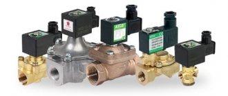
The construction market offers a wide range of these control valves, which have the same principle of operation and some differences in design. It is useful for any master or owner who independently carries out heating in his private home to know why a balancing valve is needed, the rules for its installation and settings to ensure the efficiency, economy and functionality of the heating main.
Rice. 1 Thermal imaging of a residential building with unbalanced heating
What is a balancing valve
To maintain the same temperature in the batteries, they are adjusted by changing the water flow - the less coolant passes through the radiator, the lower its temperature. You can shut off the flow with any ball valve, but in this case it will not be possible to set and adjust the same temperature in the devices if there is more than one heating device. It will have to be measured with temperature sensors on the surface of the batteries and by rotating the valve to experimentally set its desired position.
Balancing valves, which are widely used for adjustment, effectively solve the problem of maintaining balance automatically or through simple calculations of the required flow rate and the corresponding settings in the devices. Structurally, the device partially blocks the flow of the coolant, reducing the cross-section of the pipes, similar to any shut-off valve, with the difference that the required supply volume is accurately set on the adjustment scales using the rotary handle of the mechanism or automatically.
Why use it
Installing balancing valves in the heating system, in addition to maintaining the same temperature of the radiators, in an individual home brings the following effect:
- Precise adjustment of the coolant temperature allows you to set its value depending on the purpose of the premises - in living rooms it can be higher, in utility rooms, storerooms, workshops, gyms, and food storage areas, you can set it lower using balancers. This factor increases the comfort of living in the house.
- Changing the coolant flow using a balance valve regulator depending on the purpose of the premises brings a significant economic effect, allowing you to save on fuel.
- In winter, when the owners are absent, constant heating of the home is necessary - with the help of balancing valves, you can adjust the heating system with minimal fuel consumption and maintain a constant temperature in all rooms. This advantage also saves financial resources for the owners.
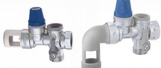
Rice. 3 Manual balancing valves for heating and hot water supply (DHW) systems in the house
Types of valves
Valves are divided into two types:
- Static (manual).
- Auto.
Manual balancing valve
Advantages of manual type:
- Works great at stable pressure.
- Suitable for houses and apartments with a small number of radiators.
- Helps carry out repair work without turning off the entire heating system.
Note! The manual type of balancing valve will work effectively only if the number of radiators in the room does not exceed 5 units.
Automatic valve
More batteries will cause the valves to malfunction. When the thermostat on the first radiator is closed, the water flow on the second will increase. As a result, the coolant in some batteries will reach a boil, while in others, at best, it will only heat up slightly.
We recommend that you read: How to choose and install a water tap?
The solution to this situation is to install automatic valves.
Such balancing mechanisms are installed on risers or branches equipped with a large number of batteries.
According to the principle of its operation, the balancing valve of this sample is slightly different from a mechanical one.
The valve is set to the position of maximum water flow. When the coolant consumption by the thermostat of one of the radiators decreases, the pressure will increase. It is at this moment that the capillary tube comes into action. It operates an automatic valve that instantly analyzes the pressure difference. The flow adjustment occurs so quickly that the next thermostats do not even have time to close.
The result is a constantly balanced system.
Advantages of automatic type:
- The presence of a capillary tube ensures instant activation of the adjustment mechanism.
- Maintains stable pressure readings, despite their fluctuations caused by the operation of thermostats.
- Such valves are used when there are a large number of batteries around the entire perimeter.
- It is possible to create “independent zones”.
Note! Regardless of the brand, each manufacturer offers quality products. Therefore, there are no strict criteria for choosing a product.
Design and operating principle
The principle of operation of balancing valves is to block the flow of liquid with a retractable valve or rod, causing a reduction in the cross-section of the passage channel. The devices have different designs and connection technologies; in a heating system they can additionally:
- Maintain the pressure drop at the same level.
- Limit coolant consumption.
- Shut off the pipeline.
- Perform drain functions for working fluid.
Structurally, balancing valves resemble conventional valves; their main elements are:
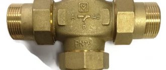
- Brass body with two through pipes with internal or external threads designed to connect to a line with standard pipe diameters. The connection in the pipeline, in the absence of a threaded fitting with a movable threaded nut (American), is made through its analogues - additional adapter couplings with different union nuts.
- A locking mechanism, the movement of which regulates the degree of blocking of the coolant passage channel.
Rice. 4 Danfoss LENO MSV-B manual balancing valve
- Adjustment handle with scale and setting indicators, allowing you to adjust the flow inside the device.
- Modern models are equipped with additional elements in the form of two measuring fittings, with the help of which the flow volumes (throughput) are measured at the inlet and outlet of the device.
- Some models are equipped with a shut-off ball mechanism that allows you to completely shut off the flow, or have the function of draining liquid from the water supply.
- High-tech modern types can be controlled automatically; for this, instead of a rotating head, a servo drive is installed, which, when power is supplied, pushes the locking mechanism, and the degree of channel closure depends on the amount of voltage applied.
Rice. 5 Danfos AB-QM automatic balancers - design
Operating principle
Balancing valves are designed to use them to achieve maximum efficiency of all heating elements of the system, as well as to adjust it at any time.
We recommend that you read: Design of a three-way ball valve
The principle of operation of the device is that the valve changes the flow area through the operation of parts.
When the handle designed for adjustment is rotated in either direction, torque is transmitted to the nut and spindle. Unscrewing causes the last element to rise from the lower position to the upper one. Being at the bottom, it tightly blocks the flow, preventing coolant from passing through the pipes.
Thus, when the valve is unscrewed, the spool allows a certain amount of energy to pass through, increasing the passage; when it is tightened, the passage narrows, which reduces or completely blocks the flow. Rotating the spindle changes the throughput of the device.
Any adjustment of the flow area entails a change in the valve’s resistance to the flow of water or any other coolant.
Water, just like any other energy carrier, always follows the path of least resistance. As a result, distant heating circuits do not heat up enough. The balancing valve creates artificial resistance in the path of water, accelerating its flow to distant circuits. Thus, the device provides the calculated pressure drop.
With such work, the main task of the entire structure is to ensure maximum tightness. To do this, manufacturers use several options for sealing rings:
- from fluoroplastic;
- made of thick rubber;
- made of metal.
For precise tuning, you need to study the technical specifications, which describe the operation of the system at certain shutter positions.
Types of balancing valves
Balancing in heating systems is carried out using two types of control valves:
- Manual . The design is a body made of non-ferrous metals (bronze, brass), which houses a balancing element, the degree of extension of which is set by turning a mechanical handle.
- Automatic . Automatic devices are installed on the return pipeline together with partner valves that can limit the flow of the medium by presetting the throughput. When connected, they are connected to partners via an impulse tube connected to the built-in measuring nipple. If the fitting is installed to supply water in a direct line, its handle is red; when installed in a return line, it is blue (Danfoss models). Automatic types include models controlled by a servo drive, which is supplied with constant voltage.
What is it needed for
As the name suggests, this device is used to balance the heating system. The main task of such operations is considered to be uniform heat distribution in all branches of the system. Thus, each of the installed radiators will be able to receive the required amount of coolant at a certain temperature.
Note! When talking about setting up the system, we mean the preliminary coolant flow for the efficient operation of each section.
In pipelines that are simple in design, the heat flow can be balanced by correctly selecting the pipe diameter. In complex systems with several branches, regulation of the amount of heat per individual circuit occurs with the participation of special washers, the displacement of which allows you to set the required pipe diameter for the passage of coolant.
Please note that all the described methods are considered obsolete. At the moment, a special control valve is installed in heating systems, assembled according to the principle of a valve. Two fittings are installed in the device body, which are used for the following purposes:
- Measuring water pressure in the system before and after passing through the valve;
- A special capillary tube is connected to regulate the operation of the device.
Manual balancing valve
During pressure measurement, each of the involved fittings determines its value, as well as the parameters of the differential after passing through the regulator. Based on the data obtained from the instructions for the device, you can calculate the required number of turns of the handle for normal water flow in the heating system.
Note! Balancing valves from some well-known manufacturers, for example, the Danfoss brand, have a special digital display, from which the consumer can find out about the amount of liquid flowing through the pipes. The main disadvantage of such devices is the high price.
Balancing valve for heating system
Existing heat supply systems are conventionally divided into two types:
- Dynamic. They have conditionally constant or variable hydraulic characteristics, these include heating lines with two-way control valves. These systems are equipped with automatic balancing differential regulators.
- Static. They have constant hydraulic parameters, include lines with or without three-way adjustment valves, the system is equipped with static manual balancing valves.
Rice. 7 Balancing valve in the line - installation diagram of automatic fittings
In a private house
In a private house, a balance valve is installed on each radiator; the outlet pipes of each of them must have union nuts or another type of threaded connection. The use of automatic systems does not require adjustment - when using a two-valve design, the supply of coolant to radiators installed at a large distance from the boiler is automatically increased.
This occurs due to the transfer of water to the actuators through a pulse tube under lower pressure than that of the first batteries from the boiler. The use of another type of combined valves also does not require calculating heat transfer using special tables and measurements; the devices have built-in control elements, the movement of which occurs using an electric drive.
If a manual balancer is used, it must be adjusted using measuring equipment.
Rice. 8 Automatic balancing valve in the heating system - connection diagram
To determine the volume of water supplied to each radiator and, accordingly, balancing, an electronic contact thermometer is used, with which the temperature of all heating radiators is measured. The average supply volume per heater is determined by dividing the total value by the number of heating elements. The greatest flow of hot water should flow to the furthest radiator, a smaller amount to the element closest to the boiler. When carrying out adjustment work using a manual mechanical device, proceed as follows:
- Open all control valves all the way and turn on the water; the maximum surface temperature of the radiators is 70 - 80 degrees.
- Using a contact thermometer, measure the temperature of all batteries and record the readings.
- Since the furthest elements must be supplied with the maximum amount of coolant, they are not subject to further regulation. Each valve has a different number of revolutions and its own individual settings, so the easiest way is to calculate the required number of revolutions using the simplest school rules based on the linear dependence of the radiator temperature on the volume of passing coolant.
Rice. 9 Balancing fittings - installation examples
- For example, if the operating temperature of the first radiator from the boiler is +80 C., and the last +70 C. with the same supply volumes of 0.5 m3/h, on the first heater this indicator is reduced by a ratio of 80 to 70, consumption will go less, and the resulting volume will be 0.435 m3/h. If all the valves are not set to the maximum flow, but set to the average value, then you can take the heaters located in the middle of the line as a guide and similarly reduce the throughput closer to the boiler and increase it at the farthest points.
In a multi-storey building or building
The installation of valves in a multi-storey building is carried out in the return line of each riser; if the electric pump is far away, the pressure in each of them should be approximately the same - in this case, the flow rate for each riser is considered equal.
To set up in an apartment building with a large number of risers, it uses data on the volume of water supplied by an electric pump, which is divided by the number of risers. The resulting value in cubic meters per hour (for the Danfoss LENO MSV-B valve) is set on the digital scale of the device by rotating the handle.
How to adjust radiator network balance
Each valve comes with instructions upon purchase, which contain information on how to calculate the number of turns of the handle.
Using the attached diagram, you can permanently regulate energy consumption, saving on heating.
According to the instructions, you need to turn the valve to a certain level.
There are two ways to adjust the valve.
Method 1
Experienced specialists have a simple and proven way to adjust the system.
They divide the valve speed by the number of radiators located around the entire perimeter of the room. It is this method that allows them to accurately determine the flow adjustment step. The principle is to close all taps in the reverse order - from the last to the first radiator.
For a more clear example, let's take the following system characteristics.
The dead-end system has 5 batteries, which are equipped with manual valves. The spindle in them is adjustable by 4.5 turns. It is necessary to divide 4.5 by 5 (the number of radiators). The result is a step of 0.9 turns.
We recommend that you read: Why do you need a check valve for water and how to install it correctly?
This means that the following valves must open the following number of turns:
| First balancing valve | by 0.9 revolutions. |
| Second balancing valve | 1.8 revolutions. |
| Third balancing valve | 2.7 revolutions. |
| Fourth | 3.6 revolutions. |
Method 2
There is another, very effective way of adjustment. It is carried out faster, and includes the ability to take into account the individual features of each radiator. But to carry out such an adjustment, you will need a special contact-type thermometer.
The whole process proceeds in the following sequence:
- Open all valves without exception and allow the system to reach an operating temperature of 80 degrees.
- Measure the temperature of all batteries using a thermometer.
- Eliminate the difference by closing the first and middle taps. The latter mechanisms do not need to be adjusted. As a rule, the first valve turns a maximum of 1.5 turns, and the middle ones - 2.5.
- Do not make any adjustments for 20 minutes. After adapting the system, take measurements again.
The main task of this method, like the previous one, is to eliminate the difference in temperature at which all batteries in the room heat up.
Valve installation
When installing the valve, it is necessary to place it in the direction of the arrow on the body, which indicates the direction of fluid movement, to combat turbulence, which affects the accuracy of the settings. Select straight sections of pipeline with a length of 5 diameters of the device and its location points and two diameters after the valve. The equipment is installed in the return branch of the system; a plumbing adjustable wrench is sufficient to carry out the work; installation is carried out in the following sequence:
- Before installation, be sure to flush and clean the pipeline system to get rid of possible metal shavings and other foreign objects.
- Many devices have a removable head; for ease of installation in pipes, it should be removed in accordance with the instructions.
- For installation, you can use flax fiber with appropriate lubricant, which is wound around the end of the pipe and the battery outlet fitting.
- The control valve is screwed onto the pipe at one end, the other is attached to the radiator with special washers (American adapter coupling), which is placed on the outlet radiator fitting or screwed into the valve, playing the role of a connecting coupling.
Setting the balance valves
To balance the heating in a private house, select manual devices of the required diameter, selecting and configuring them using the appropriate diagram included in the passport. The initial data for working with the graph are the supply volume, expressed in cubic meters per hour or liters per second, and the pressure drop, measured in bars, atmospheres or Pascals.
For example, when determining the position of the adjustment indicator of the MSV-F2 modification with a nominal bore DN equal to 65 mm. at a flow rate of 16 cubic meters per hour. and pressure drops of 5 kPa. (Fig. 11) on the graph, connect the points on the corresponding flow and pressure scales and extend the line until the conventional scale intersects the coefficient Ku.
From the point on the Ku scale, draw a horizontal line for diameter D equal to 65 mm, find the setting with the number 7, which is set on the handle scale.
Also, for the selected diameter of the device, its adjustment is carried out using the table (Fig. 12), from which the number of spindle revolutions corresponding to a certain flow is determined.
Rice. 11 Determination of the position of the valve scale at a known pressure and a certain water supply
Rice. 12 Example table for manual configuration
Technical characteristics of the Broen Ballorex valve
Using the Ballorex valve, balancing can be carried out with a fairly high degree of accuracy. This valve can function as a manually adjustable valve and a ball valve with a locking mechanism.
Bollorex balancing valve device (inside view)
The main purpose of the “BROEN BALLOREX” valve:
- balancing and regulation via hydraulics;
- limiting and measuring the flow of the working medium, as well as opening or closing its flow in the system;
- measuring the temperature of the working environment.
The Ballorex valve is produced in a variety of designs, the nominal diameter can be in the range of DN 15 - DN 600, and the pressure from PN16 to PN25 bar. Depending on the nominal diameter of the passage and pressure, flange, threaded or welded connection methods are used. Broen Ballorex fittings are used in pipelines with a working environment temperature from -20 ºC to +135 ºC.
Broen Ballorex balancing valves with a passage diameter from 15 to 50 mm have a brass body, and fittings with a diameter of DN65 - DN200 are made of high-strength steel for a flanged connection method or for threading.
Static balancing valve “Ballorex”
Ballorex balancing valves and ball valves can be installed almost anywhere in the pipeline and in any position.
Advantages of Ballorex balancing valves
Thanks to the narrow specialization of the Broen brand, valves of this brand have a number of undeniable advantages:
- A wide range of fittings, covering various diameters and operating parameters, makes it possible to choose the best option for highways for a wide variety of purposes.
- The design features of the valve, which are based on a ball valve, allow you to regulate the flow or open and close the flow of the working medium anywhere in the pipeline.
- Minimal restrictions on the installation location of the valve make it an almost universal fitting.
- Together with the balancing valve, a hexagonal valve is supplied, with the help of which the working flow is regulated.
Ballomax and Ballofix fittings
In addition to balancing valves, the Broen company also produces other types of fittings. Ballomax ball valve is designed for gas distribution lines, cooling and heat supply systems, as well as for the transportation of mineral oils.